7
Before Using
Connections
Other Information
Operation
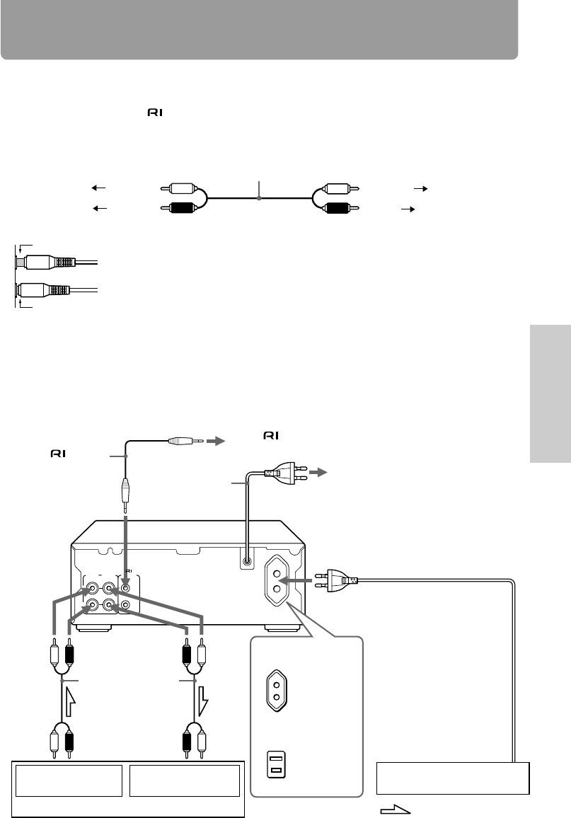
Connecting to other components
Before connecting
• Do not connect the AC power cord (mains lead) until you have completed all the other
connections including the
connections on the next page.
• On each pair of connectors, a red connector (marked R) corresponds to the right channel, and a
white connector (marked L) to the left channel. Connect white plugs of audio connection cables
to L connectors and connect red plugs of audio connection cables to R connectors .
• Insert the plug securely. If the connection is incomplete, noise or malfunction may result.
• Bundling an audio connection cable with the power cord or speaker cord may degrade the sound
quality.
•
To use the unit with the other ONKYO Separate Collection Series components, follow the connection
diagram in the A-905TX or R-805TX instruction manual to connect the unit to the system.
Note:
The 230-240 V model is shown in the following illustrations.
Audio connection cable
To L connectors (White)
To R connectors
(Red)
(White)
To L connectors
(Red)
To R connectors
Improper connection
Insert completely
REMOTE
CONTROL
(REC) (PLAY)
INPUT
OUTPUT
L
R
To the connector on the other ONKYO
component (See next page.)
To a wall outlet (the mains)
(See next page.)
Supplied remote
control cable
AC power cord
(mains lead)
Red
(Right)
White
(Left)
Red
(Right)
White
(Left)
Supplied audio
connection cable
White
(to L)
White
(to L)
Red
(to R)
Red
(to R)
To the TAPE
OUTPUT (REC) jacks
To the TAPE
INPUT (PLAY) jacks
Amplifier
Other component
: Signal flow
To the AC OUTLET (UNSWITCHED)
connector
The AC power cord (mains lead) of the
other component can be connected to
this AC OUTLET connector.
Note on the AC OUTLET
connector
The shape, number, or total
capacity of the AC outlets
may differ depending on the
area where the unit is
purchased.
Capacity is
100 watts.
230-240 V, 50 Hz
models
Capacity is
120 watts.
120 V, 60 Hz models


