22
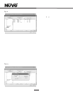
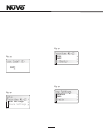
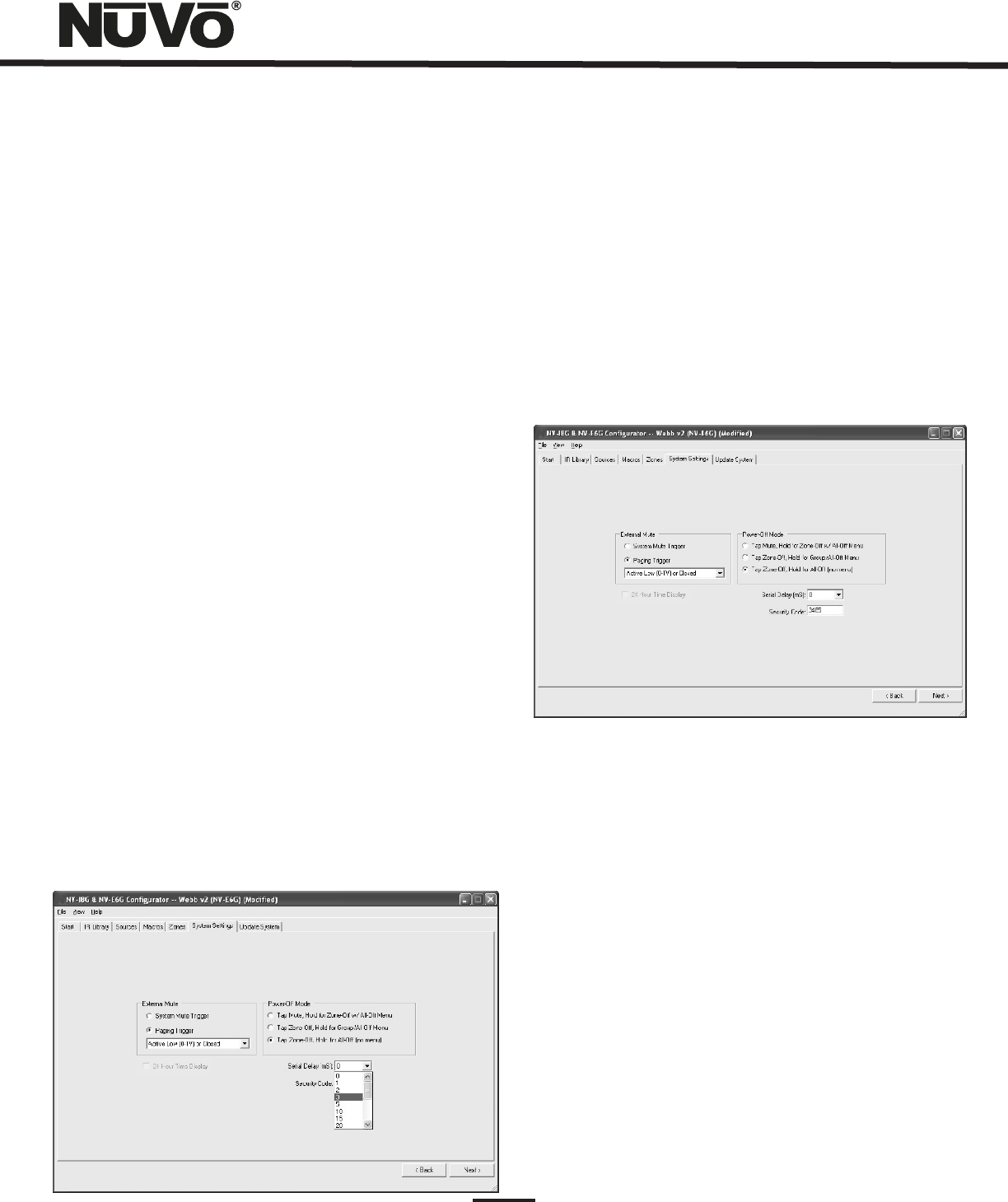
Fig. 29
6.3 24 Hour Time Display and Power Off Mode
24 Hour Time Display: Time display is not functional on the
Essentia model. This will appear grayed out when the
Configurator software is in NV-E6G Mode
Power Off Mode: The Essentia Configurator allows the option
for three power off modes.
Tap Mute/Hold for Zone-Off w/ All-Off Menu: This mode
causes a temporary zone mute when the Control Pad power
button is tapped. When it is held for three seconds, a menu
will appear with the option to turn the zone off or turn all the
zones off.
Tap Zone-Off/Hold for Group/All-Off Menu: In this mode a
single tap of the power button turns the zone off and holding
the power button causes a second menu that gives the
option to turn off that zone s group or turn all the zones off.
Tap Zone-Off/Hold for All-Off (no menu): This is the default
choice. In this mode, a tap turns the zone off and holding the
power button turns all the zones off.
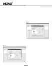
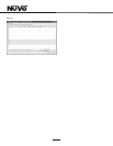
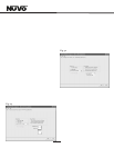
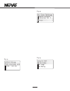
6.4 Serial Delay (Fig. 29)
This drop down menu provides a choice of delays measured
in milliseconds. This is only necessary when you are using
the RS232 communication for third party control of the
Essentia System. This utility slows the rate at which
information is delivered to the home automation system
from the Essentia. This is sometimes necessary to allow the
home automation s processor time to buffer the incoming
information.
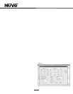
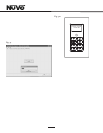
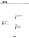
6.5 Security Code (Fig. 30)
A feature with the zone setup of the Essentia System is
the ability to lock the zone. This can be done as a default
that will require a four-digit security code to unlock the
zone Control Pad when the zone is turned on, or it can be
done as a temporary setting from the Control Pad menu to
lock the zone on its current listening choice. In either
scenario, the security code must be set to unlock the
zone. The security code can be any four digits or left at
the default 5555.
Fig. 30
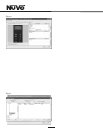
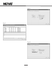
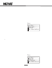
7. Update System (Fig. 31)
The finished configuration is now ready to be downloaded
to the Essentia amplifier. While downloading, a progress
box will show download progress. Once complete, the
configuration is permanently stored in flash memory.
Configurations can always be retrieved and edited at a
future date.
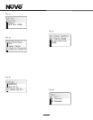
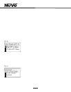
Control Pad Firmware Update (Fig. 31a)
When first plugged in and addressed, the Control Pads
will poll the main unit for the correct firmware version. If
they are at a lesser version number an upgrade notice will
appear on the display. It is important to allow this process
to complete. When the Control Pad is finished upgrading
itself it will turn off. At that point, it is ready for zone
control use.


