


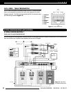
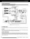
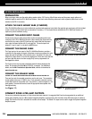
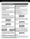
Figure 10. Proper connection of audio input cables
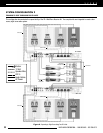
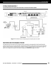
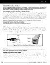
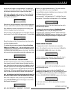
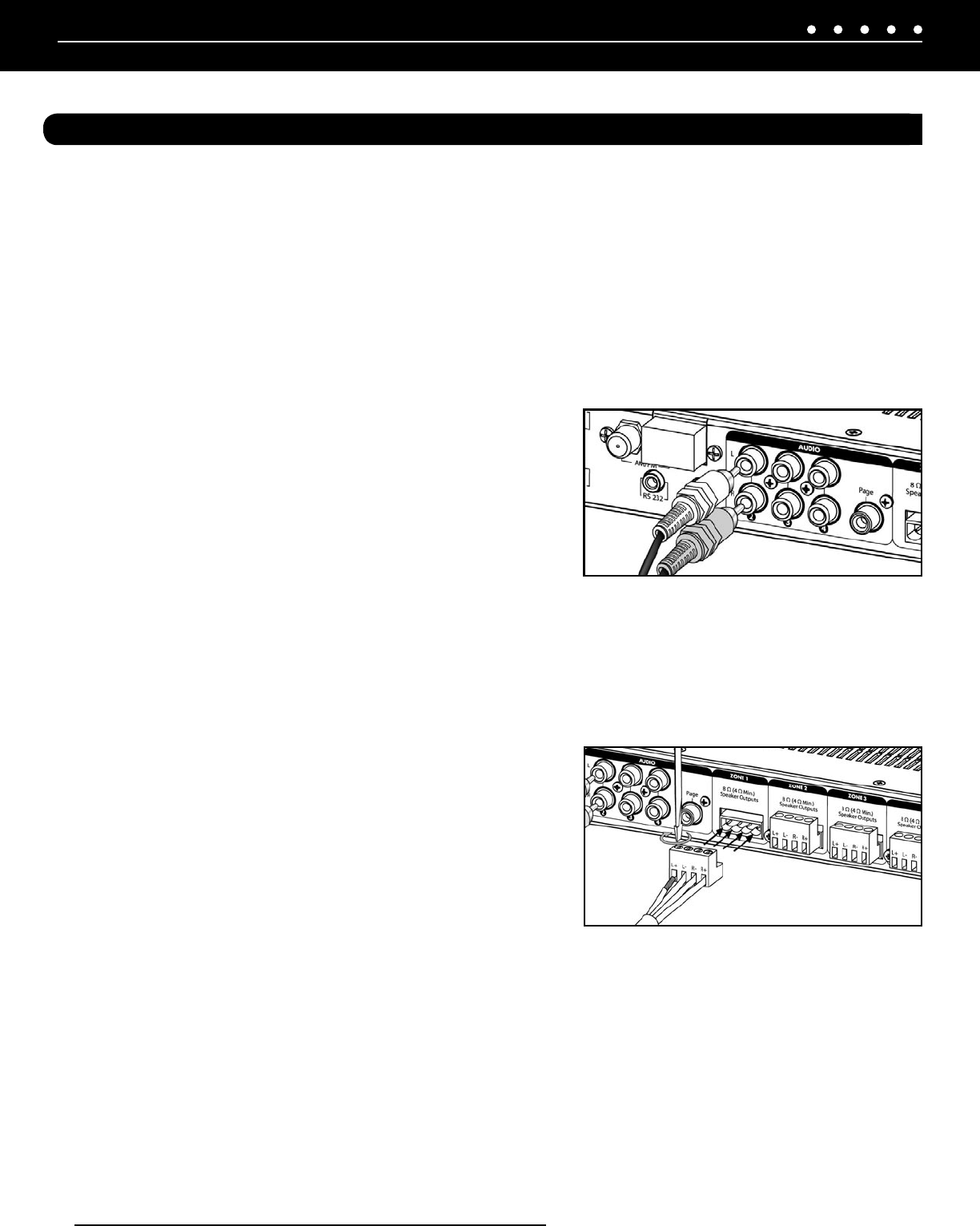
Figure 11. Connecting Loudspeakers to ZR-4
MultiZone Receiver
NILES AUDIO CORPORATION – 1-800-BUY-HIFI – 305-238-437314
SYSTEM INSTALLATION
PREPARATION
Before you begin, make sure the audio cables, speaker cables, CAT-5 wiring, MicroFlasher wires and the power supply cable are of
sufficient length to reach the ZR-4 MultiZone Receiver. Label each cable describing where each cable originates (rather than to which
terminal on the ZR-4 it connects).
ATTACH THE RACK MOUNT EARS (IF NEEDED)
If the ZR-4 MultiZone Receiver is to be installed into a professional equipment rack, attach the supplied rack mount ears with the included
screws. The four non-slip plastic feet are removable, if necessary. A 1U vent panel above and below the ZR-4 MultiZone Receiver are
required to provide maximum cooling.
CONNECT THE AUDIO INPUT CABLES
Connect each source’s audio output cables to the corresponding audio input
connection of the ZR-4 MultiZone Receiver. When making the connections be
sure that the two audio cable RCA jacks are fully seated and that the proper
color code is followed (white=left ch; red=right ch). The audio inputs are
labeled 2,3, and 4. Input 1 is the built-in AM/FM tuner.
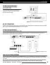
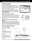
CONNECT THE PAGING CABLE
The Page input on the rear panel of the ZR-4 MultiZone Receiver provides a
connection for the paging out signal of telephone or intercom systems for voice
paging through the speakers in the listening zones. By default, all zones will
respond to a page when it is input to the paging port. If there are zones that the
end-user does not desire to receive a page, they can be programmed out.
See Page 19 for details.
The Page input can also be used to distribute doorbell chimes throughout the
house. An accessory, the Niles DBI-1 (FG01034), is required. For installation
details, see the DBI-1 Installation & Operation Guide, available for download at
www.nilesaudio.com.
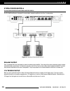
CONNECT THE SPEAKER WIRES
CAUTION! ALL SPEAKER WIRE CONNECTIONS MUST BE MADE WITH THE RECEIVER OFF.
There are four sets of removable connectors, one for each zone. The connectors
accept speaker wires up to 16 AWG in size. Each removable connector has four
screw-down terminals for speaker wire: One positive (+) and one negative (-) for
each speaker. Unscrew the terminal, insert the appropriate bare speaker wire,
then tighten firmly.
(See Figure 11).
CONNECT ZONE 4 PRE-AMP OUTPUTS
If a zone is a particularly large area, or if high volume levels are required, it is suggested that Zone four be augmented by an additional
stereo power amplifier, such as a Niles System Integration Amplifier, connected to the Pre Out with a stereo RCA audio cable of sufficient
length. The Zone four Pre Out is selectable for variable or fixed output. The Global 12V output can be used to trigger the System Integration
Amplifier’s power.