


13
CONFIGURING YOUR SYSTEM
CONFIGURING YOUR SYSTEM
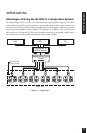
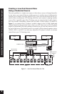
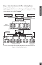
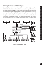
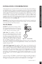
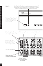
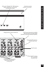
The SI-1260 offers many configuration possibilities. Therefore, carefully plan the
installation before starting. Start by drawing a block diagram of your system and use
the Configuration Worksheet on page 29 to document how you plan to connect your
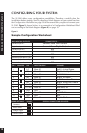
SI-1260. Figure 9, shown below, is an example of a Configuration Worksheet filled
out according to the block diagram (figure 6) on page 10.
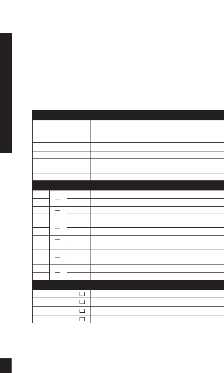
Sample Configuration Worksheet
Figure 9
BUS INPUTS & OUTPUTS CONNECTED TO. . .
Left Bus Input # 1 Second Zone Left Output
Right Bus Input # 1 Second Zone Right Output
Left Bus Input # 2 N/S
Right Bus Input # 2 N/S
Cascade Output Bus # 1 Right N/S
Cascade Output Bus # 1 Left N/S
Cascade Output Bus # 2 Right N/S
Cascade Output Bus # 2 Left N/S
CH # BRIDGED DIP INPUT SOURCE SPEAKER
1 L1 Bus #1 Left Living Room
2 R1 Bus #1 Right Living Room
3 L1 Bus #1 Left Kitchen
4 R1 Bus #1 Right Kitchen
5 L 1 Bus #1 Left Exercise Room
6 R1 Bus #1 Right Exercise Room
7 L1+R1 Bus #1 Hallway #1
8 L1+R1 Bus #1 Hallway #2
9 Off N/S N/S
10 L1 Bus #1 Left Patio
11 Off N/S N/S
12 R1 Bus #1 Right Patio
MODE SETTINGS IN USE SPECIAL CONNECTIONS OR NOTES
Constant
Audio Sense
Voltage Trigger
Control Output
✓
✓
✓