


20
INSTALLATION
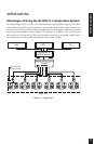
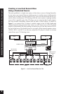
BusMatrix
™
Input DIP Switch Settings
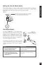
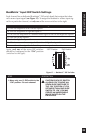
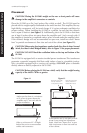
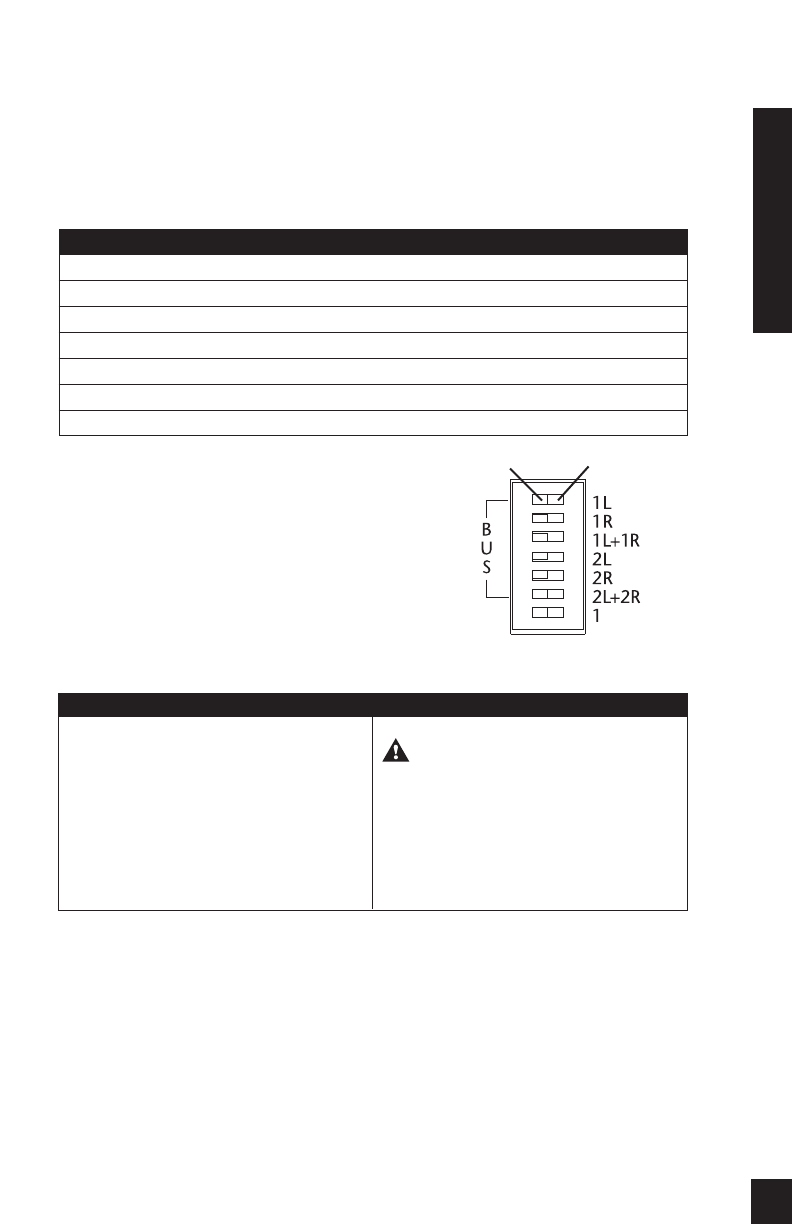
Each channel has a dedicated BusMatrix
™
DIP switch bank that assigns that chan-
nel’s source input signal (see Figure 15). To assign the BusMatrix
™
source input sig-
nal for a particular channel, set only one of the seven switches to the right.
Again, only one of the seven DIP switches
should be configured to the “ON” position
(switched to the right).
STEP
1. Move only one (1) DIP switch to the
“ON” position for each channel.
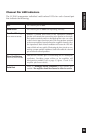
DESCRIPTION
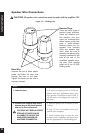
CAUTION! EACH DIP SWITCH
ALLOWS YOU TO MOVE ALL
SEVEN SLIDE SWITCHES TO
THE “ON” POSITION. IF YOU
SET MORE THAN ONE SLIDE
SWITCH TO “ON” YOU MAY
CREATE AN UNDESIRABLE
MIX OF INPUTS ON THE
ENTIRE BUS.
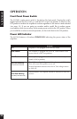
“ON” Position“OFF”Position
DIP Switch Settings
1L is for the assignment of the Left Bus Input #1
1R is for the assignment of Right Bus Input #1
1L+1R is for the assignment of a summed mono signal of the Left and Right Bus Input #1
2L is for the Left Bus Input #2
2R is for the Right Bus Input #2
2L+2R is for a summed mono signal of the Left and Right Bus Input #2
The seventh switch assigns the dedicated input to its respective channel
Figure 15 — BusMatrix
™
DIP Switches