


Installation Considerations
IPC-6 Total Power Capacity
Check that the total power consumption of all the devices
plugged into the IPC-6 does not exceed 1500 watts. If the
total power is greater than 1500 watts, you will need to trig-
ger a Niles AC-3 voltage controlled power strip from one of
the IPC-6's 12 volt control outputs. Since the maximum
power output of most home outlets is 1500 watts, you'll
need to plug the AC-3 into a wall outlet that is on a different
circuit breaker than the IPC-6.
IPC-6 Low Voltage Contacts (C1 & C2 Controlled
Outputs)
The IPC-6 has both normally-open and normally-closed con-
tacts to control devices that need a switch to control them.
These are low voltage contacts only. DO NOT connect 120
volts AC to these contacts.
12 Volt Trigger Inputs
The IPC-6's external trigger inputs accept 3-30 volts AC or DC.
Switched 120 Volt AC Outlets
Test each component to determine whether it has the “latch-
ing" type of power control. Start by turning the component
on. Next, unplug its AC power cord. Wait 5 minutes, then
plug it back in. If the component returns to its fully “on”
state rather than to a “standby” state it is suitable for use
5
I
NTELLIGENT
P
OWER
C
ONTROLLER
IMPORTANT
Do not exceed 1500
watts of total power
consumption for the
devices plugged into
each IPC-6.
IMPORTANT
Do not connect 120
volt AC power to the
C1 and C2 terminals,
they are low voltage
only!
IMPORTANT
Do not connect any
signal higher than 30
volts to the trigger
inputs!
with a switched AC outlet on the IPC-6.
Installation
1. Select a convenient location for the IPC-6.
2. Run all the necessary wiring to the IPC-6’s planned loca-
tion. Label the wires with both their origin (which compo-
nent they power) and their destination (which of the
switched outlets that component will use). Use the
Programming Worksheet on Page 17 to write down your
choices. You will need a convenient written record when you
program your IPC-6.
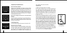
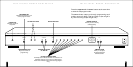
3. Make the low voltage connections to the IPC-6. If you are
using any of the low-voltage inputs or outputs, you should
remove the IPC-6’s connectors. It is easier to attach the wire
to the connector first, before putting the IPC-6 in place. To
remove a connector grasp it from the top and bottom with
your thumb and forefinger and simply pull straight back.
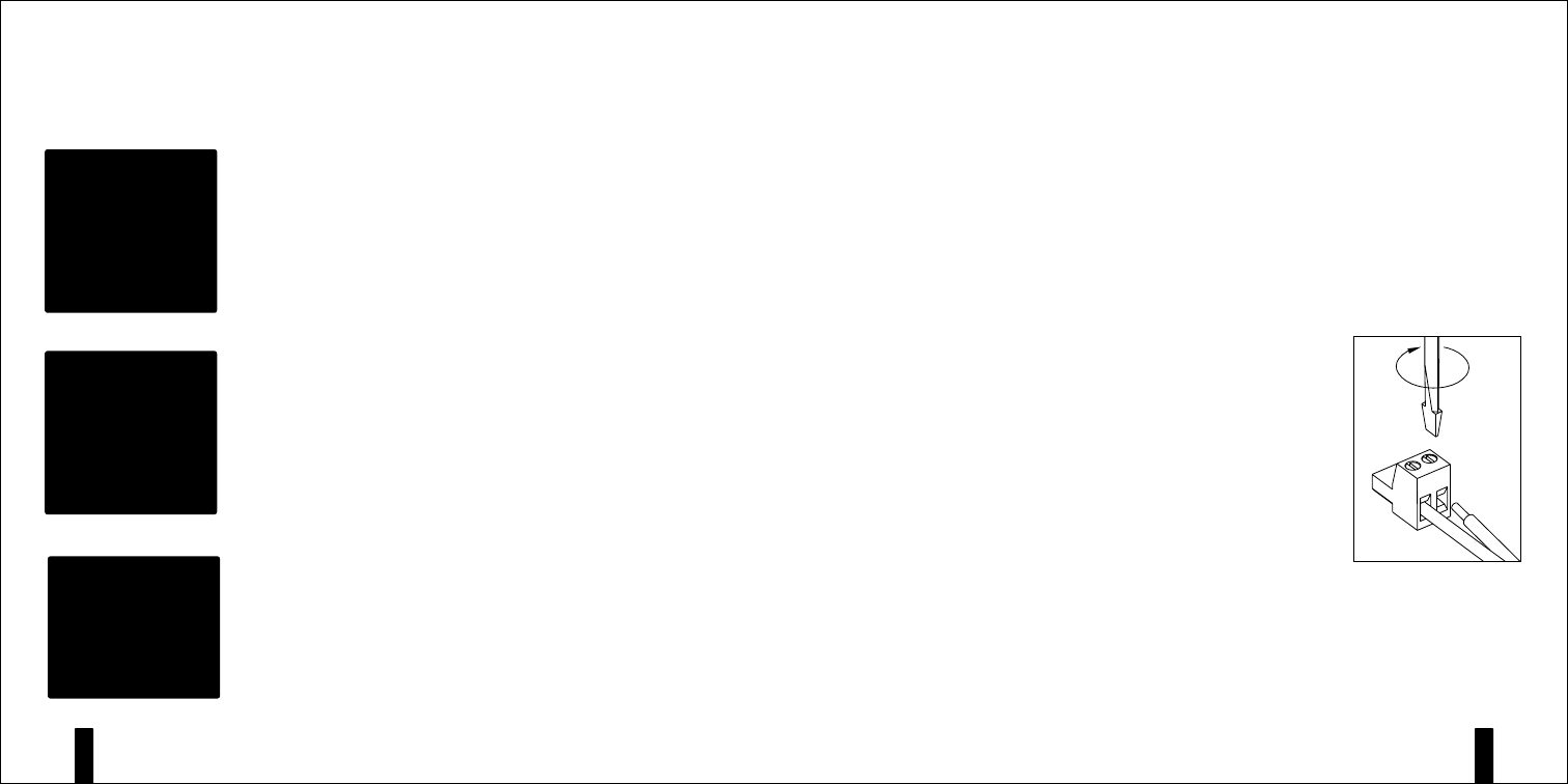
Strip
3/8” of insulation from the end of each wire. Tightly
twist the stripped wire to eliminate any frayed ends. Insert
each wire into the appropriate hole in the connector block
and tighten the terminal with an
1/8” slotted screwdriver. Be
certain that the positive terminal on the IPC-6 is connected
to the positive terminal of a 12 volt device (see Figure 1).
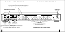
4. Put the IPC-6 into position and make the connections to it.
While carefully observing each label, plug each low voltage
connector, switched outlet plug, and triggering component
into its respective place (see Figure 2 on page 11).
6
I
NTELLIGENT
P
OWER
C
ONTROLLER
Figure1
Connecting the
Low Voltage Wires