


12
CAUTIONS AND TROUBLESHOOTING
23. Feedback
Observe care in selecting P.A. volume, transmitter location and speaker placement so that the
acoustic feedback (howling and screeching) will be avoided. Please also note the pickup pattern
characteristics of the microphone selected. Omni directional mics pick up sound equally from all
direction, and are prone to feedback if not used carefully. Unidirectional mics are more resistant to
feedback. However, they pick up sound sources best that are directly in front of the mic. Also mics
that are farther from the sound source, such as lavalier mics, required more acoustic gain and thus
are also more prone to feed back than close-source mics such as handheld or headworn models
that are used close to the mouth.
24. Microphone Damage
Headset and lavalier mic users: please note that the microphone element can easily be destroyed
by the buildup of salts and minerals from perspiration and saliva. It is good practice to put a wind-
screen on the mic at all time to protect it and to keep it clean and dry at all times.
25. No Audio
If you are not getting audio through the system, carefully re-check all setups. Especially note that
the receiver and transmitter must be set to operate on the same RF channel. Also confirm that the
Audio Mute on the transmitter is in the Off position.
26. RF Interference and Finding Open Channels
If you encounter slight receiving interference when the transmitter is far from the receiver (from
other than an operating TV station), often it can be overcome by adjusting the receiver ‘s squelch
control (SQL).
If receiving interference on a selected channel with the transmitter off, you must reprogram the
receiver and transmitter to a different channel (see sections 4, 6, 15, & 19). To reprogram, you must
first find an open channel. To do this follow the operating procedure outlined in Section 4 above,
and with the associated transmitter off, scroll through the groups/channels to find one that shows no
received signal on the receiver LCD display’s received signal icon (no bars). Also there must be no
bars either on each of the three immediately adjacent channels both below and above the selected
channel for optimum interference-free operation (so field of 7 adjacent channel total—with channel
used in the middle). If operating multiple UWS-1K systems simultaneously, repeat this procedure
with every new channel being selected, with previously tuned systems all ON, both transmitters and
receivers.
Please note that wireless frequencies are shared with other radio services. According to FCC
regulations, wireless microphone operations are unprotected from interference from other licensed
operations in the band. If any interference is received by any Government or non-government
operation, the wireless microphone must be cease operation or change frequencies. The above
statement is valid only for use in the U.S.A.
5
6. Selecting the UH/UB-1K Transmitters Group &
Channel Setting
Both the UH/UB-1K transmitters have to be programmed for the channel and group selected on
the UWS-1K receiver via the IR reception link between the receiver and transmitter during the first
20 seconds after the transmitter is powered up. As soon as the transmitter LEDs light up indicat-
ing Power ON, the Transfer Button (18) on the UWS-1K receiver must be pressed once while the
MAIN MENU is being displayed. The Power LED (9) of the receiver will flash quickly indicating IR
transmission to the transmitters of the Group and Channels selected on the receiver is in progress.
Successful transfer is complete when the Signal Strength indicator on the receiver’s LCD Display
(10) indicates a received signal from the transmitter being programmed. Press Transfer (18) again
to stop when this happens or just let it expire in 20 seconds automatically. (Important note: there is
no other way to program the Group and Channel selected in the UWS-1K receiver into the UH/UB-
1K transmitters so the above procedure must be followed carefully.)
SYSTEM OPERATION
UWS-1K RECEIVER
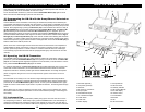
7. Rack-mounting the Receiver
There are two options available for rackmounting the UWS-1K: single or side-by-side with another
UWS-1K receiver.
a. Single mounting: Just attach the optional Rack Ears (1) to each side slot and tighten with
supplied screws (as shown).
b. Side-by-side mounting: Attach the two optional Join Pieces (2) and tighten the four supplied
screws. Then attach the rack ears to each side slot and tighten with supplied screws (as
shown).
(Note: Do not mount the receiver on a rack directly above an amplifier or other source of high heat.
This could degrade the performance of the UWS-1K. Always ensure adequate airflow and heat dis-
sipation in any rack configuration.)
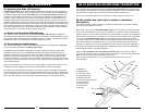
8. Installing Antennas
Install antennas by connecting the two Antennas (3) included with your system to the two RF
Screw-On Connectors (4) located on the back of your UWS-1K receiver. The optimal positions
of the antennas are 45 degrees from the receiver and 90 degree from each other. For maximum
range, it is always best to maintain a line of sight (no obstructions) between the receiver antennas
ant the transmitter at all time whenever possible.
9. Powering the Receiver
To power the receiver, plug the AD-DC adaptor (16.5VDC/0.4A) provided into the DC Input Jack
(5) on the back of the receiver. Then plug the adapter into an AC outlet. (Note: Any 16.5VDC source
with 400mA capacity can also be used.) Connect either the XLR Balanced (6) or 1⁄4” Unbalanced
Output (7) to your mixing board, effect, or amplifier.
To turn ON, press the Power Switch (8) for 2 second. The Power LED (9) will light and the LCD
Display (10) will show the Group (11), Channel (11) assignment, RF Level Meter (12), Diversity
(13), and the audio AF LED (15) displays (when the transmitter is activated).
To turn OFF, press the Power Switch (8) for 3 seconds and release. The receiver will turn off.