


6
Operation
NAD ATO LOGIC
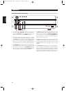
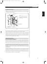
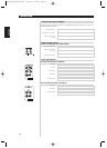
The CI-series amplifier may be turned on in any one of three discrete ways for complete system flexibility:
From the front-panel switch, the 12V-TRIGGER circuit, or by a “SLEEP/WAKE” signal-sensing circuit. The
ON/OFF power control is managed by the Automated Turn-On logic or ATO Logic circuit that requires the
amplifier to be switched back to standby in the same manner by which it was activated. In other words,
if the amplifier is switched on via a 12V-control signal, it cannot be switched to standby via the front-panel
switch, it must wait for removal of the 12V-control signal. In practice, you probably would use only one
of the methods once the NAD CI-series amplifier is installed.
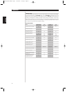
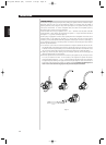
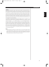
ATO LOGIC CHART
ENGLISH FRANÇAIS
DEUTSCH
NEDERLANDS
ESPAÑOL
ITALIANO
PORTUGUÊS
SVENSKA
Amber LED over
front power switch
Green
SWITCH LED
Green
12V-TRIGGER LED
Green
SENSE LED
Amber LED over
front power switch
Green
SWITCH LED
Green
12V-TRIGGER LED
Green
SENSE LED
OFF OFF OFF OFF
VACATION switch set to VACATION
SWITCH
12V TRIGGER
Amber LED over
front power switch
Green
SWITCH LED
Green
12V-TRIGGER LED
Green
SENSE LED
SLEEP/WAKE
ON OFF OFF OFF
VACATION switch set to ON
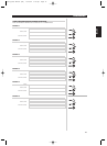
OFF ON OFF OFF
Press front power switch with
VACATION switch set to ON
ON OFF OFF OFF
Press front power switch with
VACATION switch set to ON
OFF OFF OFF OFFVACATION switch set to VACATION
ON OFF OFF OFF
VACATION switch set to ON
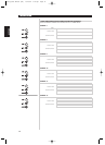
ON OFF OFF OFF
12 V INPUT TRIGGER = 0V with
VACATION switch set to ON
OFF OFF ON OFF
12V INPUT TRIGGER = 12V with
VACATION switch set to ON
OFF OFF OFF OFF
VACATION switch set to VACATION
ON OFF OFF OFF
VACATION switch set to ON
ON OFF OFF OFF
SLEEP/WAKE SENSE DEFEAT switch
set to SENSE DEFEAT with VACATION
switch set to ON
OFF OFF OFF ON
SLEEP/WAKE SENSE DEFEAT switch
set to SLEEP/WAKE and any source
input greater than 20mV with
VACATION switch set to ON
CI9120_9060 manual (GB) 12/12/02 9:09 pm Page 6