


5
Press-on Connector Cable Termination
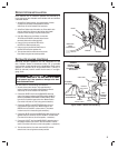
1. Gather all room, patio, and Door Station cables together
and cut them to the same length leaving approximately
12 inches entering into the wall housing. BE SURE
THAT THE CABLES REMAIN LABELED.
✔ IMPORTANT: Verify all cable run locations prior to connecting if they
were not labeled at rough-in. Incorrectly connecting cables to the Master
Station, Room Stations, or Door Stations may result in system damage.
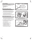
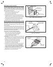
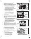
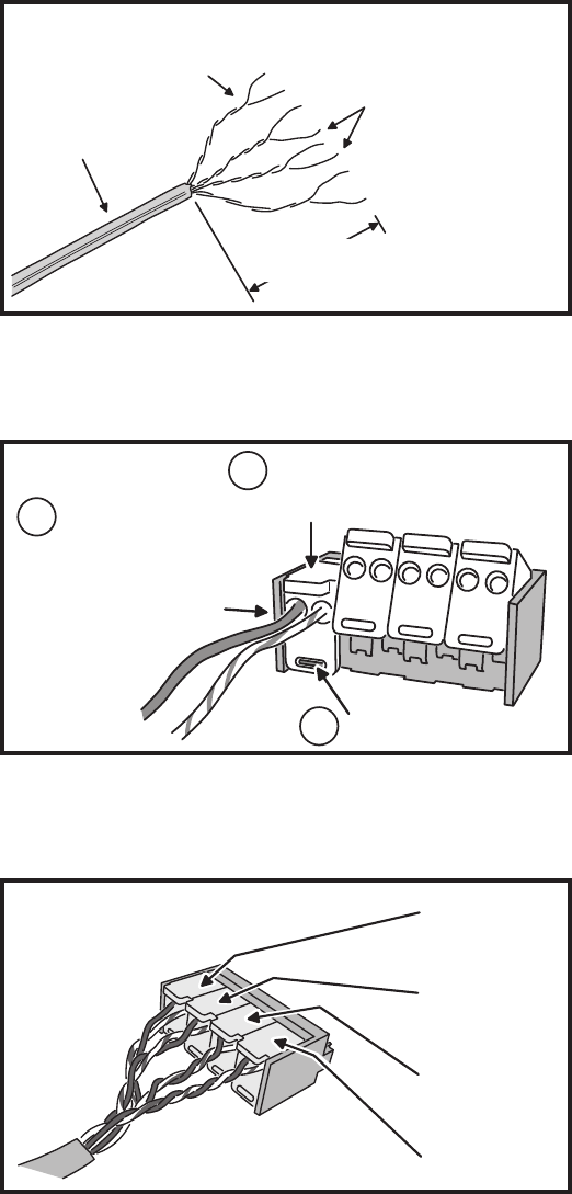
2. Strip back the outer insulation jacket of the room and Patio
Station Cat-5 cables 2 inches to expose the four color coded
twisted wire pairs inside (see Figure 10). DO NOT STRIP THE
INDIVIDUAL TWISTED PAIRS OF WIRE. The connectors
have internal sharp edge insulation displacement wire
guides that cut through the insulation on the copper wires
when the connector’s wire latches are snapped closed.
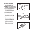
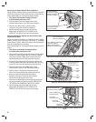
3. Open the four clear plastic wire latches on
a connector (see Figure 11).
4. Observing the color code label on the connector, insert
a wire pair (solid color wire and wire with the same color
stripe) completely into the two wire holes in the clear
plastic wire latch for that pair color (see Figure 11). BE
SURE THE WIRES ARE COMPLETELY INSERTED.
5. Hold the wires completely inserted while pressing down
fi rmly on the clear plastic wire latch. The latch will click twice
as the wires are being seated into the internal insulation
displacement wire guides. See Figure 11. VERIFY THAT
THE TAB ON THE CONNECTOR BODY IS INSIDE THE
TAB SLOT ON THE CLEAR PLASTIC WIRE LATCH.
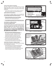
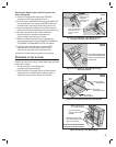
6. Repeat Steps 4 & 5 for the other three wire pairs on
the cable. Check each wire’s connection by gently
pulling on the wire. With a good connection, the wire
will not pull out of the connector (see Figure 12).
7. Repeat Steps 2-6 for each of the Cat-5 cables.
✔ NOTE: If the connector is re-opened, and any wire is removed from
the connector, cut the cable back and start over.
CAT-5 CABLE
STRIP CABLE JACKET
BACK 2 INCHES
KEEP CABLE
PAIRS TWISTED
TO REDUCE HUM
FOR PRESS-DOWN CONNECTORS
DO NOT STRIP EACH WIRE
Figure 10. Cat-5 Cable Preparation for
Press-on Connectors
PRESS
DOWN
FIRMLY
INSERT WIRE PAIRS
INTO HOLES THEN
HOLD WIRES IN PLACE
LATCH SNAPS INTO TAB
1
2
3
Figure 11. Latching Cat-5 Connector
CONNECTOR SHOWN
WITH LEVERS ON TOP
ORANGE
ORANGE / WHITE
BLUE
BLUE / WHITE
BROWN
BROWN / WHITE
GREEN
GREEN / WHITE
Figure 12. Completed Press-on Connector Assembly