


19
SETTING UP THE DSP
LOUDSPEAKERS
Connecting the loudspeakers
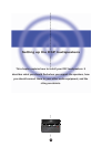
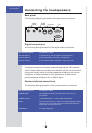
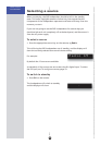
Back panel
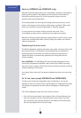
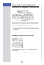
The following diagram gives details of the back panel connections:
MERIDIAN COMMS RS232
OUTPUT INPUT
DIGITAL INPUT DIGITAL
OUTPUT
21
EXPANSION
Comms
Digital
inputs
Digital
output
PC
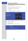
Digital connections
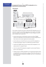
The following table gives details of the digital audio connections:
Use this connection To connect to this
DIGITAL INPUT 1, A digital source, such as a digital sound processor,
DIGITAL INPUT 2 digital preamplifier, CD player, or DVD player.
DIGITAL OUTPUT A second (slave) DSP loudspeaker, using an S5 lead.
The digital connections should be made with high-quality 75Ω screened
cable. Suitable cables are available from Meridian. We do not recommend
using audio cables, which do not have adequate shielding or the correct
impedance, or cables intended for UHF applications, as these do not
provide adequate shielding in the 1–30MHz region.
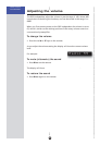
Communications connections
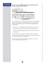
The following table gives details of the communications connections:
Use this connection To connect to this
COMMS INPUT The COMMS connection on a Meridian control unit or
preamplifier.
COMMS OUTPUT The COMMS INPUT on a second DSP loudspeaker.
RS232 The serial port of a PC, to control the DSP loudspeaker using a
computer. For more information see the Meridian Web site,
http://www.meridian-audio.com.
EXPANSION For future expansion.