


4
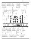
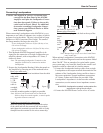
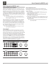
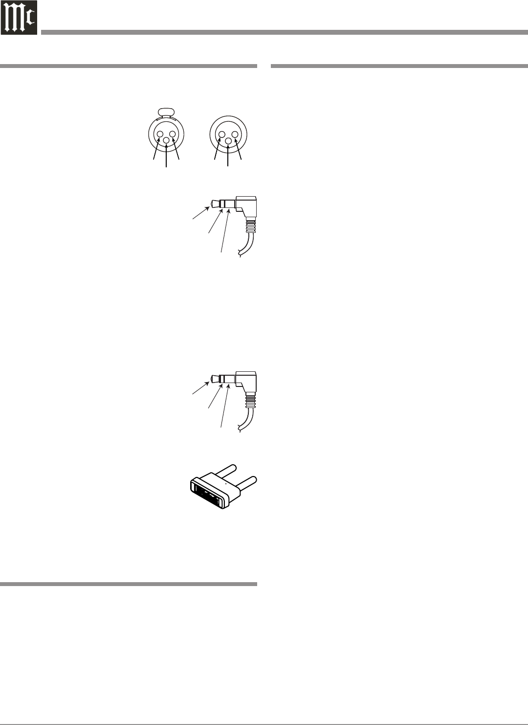
XLR Connectors
Below is the Pin configuration for the XLR Balanced Input
and Output Connectors on the MA7000. Refer to the dia-
gram for connection:
PIN 1: Shield/Ground
PIN 2: + Output
PIN 3: - Output
Power Control Connector
The MA7000 Power Control Output Jack sends Power On/
Off Signals when connected to other
McIntosh Components. A 1/8 inch
stereo mini phone plug is used for con
-
nection to the Power Control Output
on the MA7000.
Note: The Data and Power Control Connecting Cable is avail-
able from the McIntosh Parts Department:
Data and Power Control Cable Part No. 170-202
Six foot, shielded 2 conductor, with 1/8 inch stereo mini
phone plugs on each end.
Data Port Connectors
The MA7000 Data Out Ports send Remote Control Signals
to McIntosh Source Components. A 1/8
inch stereo mini phone plug is used for
connection.
McIntosh Plug-In Jumper Connector
The MA7000 utilizes a phono style Plug-In Jumper to con
-
nect the OUTPUT 1 (Preamplifier Output)
Jack to the PWR AMP (Power Amplifier
Input) Jack for each channel.
Note: The Jumper Connector is available
from the McIntosh Parts Department:
McIntosh Jumper Connector Part No. 117-781
Connector Information, Introduction and Performance Features
Connector and Cable Information
Power
Control
Ground
N/C
Data
Signal
N/C
Data
Ground
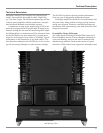
Introduction
Performance Features
PIN 2 PIN 1
PIN 3
• Power Output with Patented Autoformer
The MA7000 consists of a 250 watts per channel stereo
Power Amplifier with less than 0.005% distortion. The
McIntosh designed and manufactured Autoformer allows
connection of 2, 4 or 8 ohm Loudspeakers.
• Electronic Switching and Balanced Connections
The Preamplifier uses Logic Circuits controlling Electro
-
magnetic Switches on all inputs and operating functions
for reliable, noiseless, distortion free switching. There are
two Balanced Inputs for connection of source components
and a Balanced Preamplifier Output for driving an external
Power Amplifier.
• Power Guard
The patented McIntosh Power Guard circuit prevents the
amplifier from being overdriven into clipping with its
harsh distorted sound that can also damage your valuable
loudspeakers.
• Sentry Monitor and Thermal Protection
McIntosh Sentry Monitor power output stage protection
circuits ensure the MA7000 will have a long and trouble
free operating life. Built-in thermal protection circuits
guard against overheating.
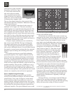
• Illuminated Power Meters
The Illuminated Power Output Watt Meters on the
MA7000 are peak responding, and indicate the power out
-
put of the amplifier.
• Power Control and Remote Control
The Power Control Output connection provides convenient
Turn-On/Off of McIntosh Source Components. The Data
Ports together with the supplied Remote Control provides
control of McIntosh Source Components connected to the
MA7000.
• Special Power Supply
The large Power Transformer, multiple filter capacitors and
regulated Power Supply ensures stable noise free operation
even though the power line varies.
• Fiber Optic Solid State Front Panel Illumination
The even Illumination of the Front Panel is accomplished
by the combination of custom designed Fiber Optic Light
Diffusers and extra long life Light Emitting Diodes
(LEDs). The glass Front Panel ensures the pristine beauty
of the MA7000 will be retained for many years.
Now you can take advantage of traditional McIntosh stan
-
dards of excellence in the MA7000 Integrated Amplifier.
The Power Amplifier section of the MA7000, with a power
output of 250 watts per channel, will drive a pair of quality
Loudspeakers to a high level of performance. The flex-
ible Preamplifier section provides connections for various
input sources and may also be used to drive an external
Power Amplifier. The MA7000 reproduction is sonically
transparent and absolutely accurate. The McIntosh Sound
is “The Sound of the Music Itself.”
PIN 2
PIN 1
PIN 3