


16
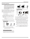
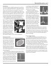
sealed with tiny leads protruding
from either end. Refer to figure
10. These leads extend into the
tube and overlap one another
with a separation of a few thou-
sandths of an inch. The leads are
made from a ferrous material that
is influenced by a magnetic field.
They are first plated with gold as a base material, then
with rhodium and finally ruthenium. Ruthenium is the best
contact material known.
The glass assembly is then placed in the center of a
multilayer coil of copper wire. The entire assembly is
molded together in a tough shock absorbing material. The
switch and coil connectors extend from the bottom in the
form of printed circuit board terminals. When a DC volt-
age is applied to the coil, current flows and creates a mag-
netic field. The force of the field causes the leads to bend
and contact one another inside the sealed glass tube. The
inert gas eliminates corrosion of the contacts and insures a
low resistance, distortion free switch.
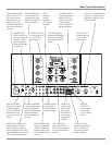
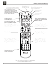
All inputs, outputs, and data ports are controlled by
logic circuits in the MA7000. The logic is changed by
front panel push-buttons or by a microprocessor IR de-
coder. This microprocessor IR decoder is programmed
with exclusive McIntosh software. It receives data from the
front panel or external sensors and provides the command
signals for input switching, data switching, and volume
control.
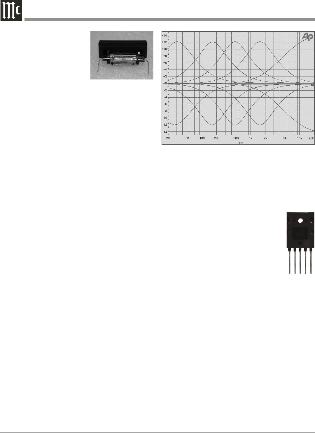
The equalizer section uses several high technology
operational amplifiers. The amplifier stage has been op-
timized for the best transient performance and minimum
distortion. Five other operational amplifiers are arranged
in a circuit configuration that is the equivalent of a series
turned circuit. A control potentiometer inserts this series
tuned circuit into either the feedback or input section of the
equalizer amplifier. This provides a 12dB boost or cut at
the frequency of the tuned circuit. Refer to figure 11. The
overall gain of the stage is 0dB when the potentiometer is
at its center detent position. In this position the tone control
elements are completely removed from the signal path.
Power Amplifier Design Philosophy
The design philosophy incorporated in the MA7000
involved several different techniques, all based on sound
scientific logic. Every stage of voltage or current ampli
-
fication must be as linear as possible prior to the use of
negative feedback. McIntosh engineers know how to prop-
erly design negative feedback circuits so they contribute to
the extremely low distortion performance expected from
a McIntosh Amplifier. The typical McIntosh owner would
never accept the approximately 100 times higher distortion
of many non-feedback designs.
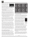
All transistors are selected to have nearly constant cur
-
rent gain over the entire current range they must cover. The
12 Power Transistors used in each channel of the MA7000
Power Output Circuitry, have matched uniform current
gain, high current bandwidth product and a large active
region safe operating area. These Power Transistors are the
very latest in semiconductor technology and
incorporate a new design known as Thermal-
Trak™. Refer to figure 12. This allows for the
instantaneous and accurate monitoring of the
Power Transistor Temperature. The MA7000
Power Output Circuitry has a specially de-
signed bias circuit to take full advantage of
the ThermalTrak™ Power Transistors and thus
precisely controls the power amplifier opera-
tion over a wide range of music conditions
with the benefits of lower distortion and cooler operation.
Precision metal film resistors and low dielectric absorption
film capacitors are used in all critical circuit locations.
The output signal of the circuit is coupled together
in the unique McIntosh MA7000 Output Autoformer.
It provides low distortion power transfer at frequencies
from below 20Hz to well beyond 20,000Hz with optimum
impedance points of two ohms, four ohms and eight ohms.
The unequaled expertise of McIntosh in the design and
manufacturing of autoformers is legendary in the high
fidelity industry.
The high efficiency circuit design of the MA7000 con-
tributes to low operating temperatures. More than 1,000
square inches of heat sink area keep the MA7000 operating
safely with convection cooling. No fans are needed.
Figure 10
Figure 11
Figure 12
ThermalTrak™ - is a trademark of Semiconductor Components Industries,
LLC (SCILLC)