


17
Technical Description, con’t
Autoformers
All solid state power amplifier output circuits work best
into what is called an optimum load. This optimum load
may vary considerably from what a loudspeaker requires.
In the case of more than one loudspeaker connected in
parallel, the load to the power amplifier may drop to two
ohms or even less. A power amplifier connected to a load
that is lower than optimum, causes more output current
to flow, which results in extra heat being generated in
the power output stage. This increase in temperature will
result in a reduced life expectancy for the amplifier.
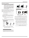
The Autoformer creates an ideal match between the
power amplifier output stage and the loudspeaker. Refer to
figure 13. There is absolutely
no performance limitation
with an Autoformer. Its fre-
quency response exceeds that
of the output circuit itself,
and extends well beyond the
audible range. Its distortion
level is so low it is virtually
impossible to measure. In the
rare event of a power ampli-
fier output circuit failure,
the McIntosh Autoformer
provides absolute protection
from possible damage to your valuable loudspeakers.
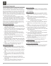
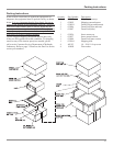
Protection Circuits
The MA7000 incorporates its version of the McIntosh
Sentry Monitor output transis
-
tor protection circuit. Refer to
figure 14. There is absolutely
no compromise in sonic per-
formance with this circuit, and
it ensures safe operation of the
amplifier under even the most
extreme operating conditions.
The different types of protec-
tion circuits incorporated in the MA7000 insure a long and
safe operating life.
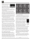
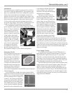
The MA7000 also includes the unique patented McIn-
tosh Power Guard circuit. Power Guard eliminates the pos-
sibility of ever overdriving the ampli-
fier into clipping. Refer to figures 15,
16 and 17. An overdriven amplifier
can produce both audible and inaudi-
ble distortion levels exceeding 40%.
The audible distortion is unpleasant
to hear, but the inaudible ultrasonic
distortion is also undesirable, since
it can damage valuable loudspeaker
system tweeters. You will never
experience the harsh and damaging
distortion due to clipping.
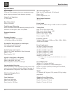
The Power Guard circuit is a
waveform comparator, monitoring
both the input and output wave
-
forms. Under normal operating con-
ditions, there are no differences be-
tween the shape of these waveforms.
If an amplifier channel is overdriven,
there will be a difference between
the two signal waveforms. When the
difference exceeds 0.3%, the Power
Guard activates the PG light and a
dynamic electronic attenuator at the
amplifier input reduces the input
volume just enough to prevent any
further increase in distortion. The
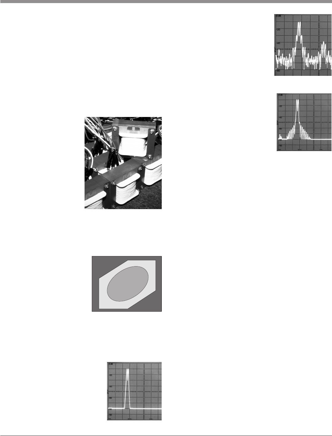
Power Guard circuit acts so fast that there are absolutely
no audible side effects and the sonic purity of the music
reproduction is perfectly preserved. The MA7000 Ampli-
fier with Power Guard is not limited to just the rated power
output, but will actually produce distortion free output well
above its rated power due to the McIntosh philosophy of
conservative design.
Power Supply Circuits
To compliment the design of the MA7000, there is a
high voltage power supply for both channels. The power
amplifiers draw high current from the AC power line.
Therefore, it is important that they plug directly into the
wall outlet. Turn on inrush current is cushioned by therm
-
istors in the power transformer’s primary circuit. This soft
start eliminates component stress during turn-on.
The MA7000 can provide greater than 50 amperes peak
output current to drive uneven speaker loads. Some poor
speaker designs have input impedance that dip to 1 or 2
ohms at various frequencies and the MA7000 has the out-
put current reserve to drive them. The MA7000 has main
filter capacitors that guarantee an excellent signal to noise
ratio and the energy storage necessary for a wide dynamic
range that music demands.
Figure 13
Figure 15
Figure 16
Figure 17
Output
Transistor
Failure
Normal Operating Area
Normal Operating Area
Sentry Monitor
Sentry Monitor
Safety Area
Safety Area
Output
Transistor
Failure
Figure 14