


10 Installation
Mounting the Stage On A Wall
NOTE: These instructions describe how to remove the stand
from the Stage and mount it to the wall. MartinLogan rec-
ommends using 4 wall anchors and machine screws to
secure the Stage bracket to the wall. When drilling pilot
holes for the wall bracket, if any screw location hits a stud,
it is recommended to directly screw a lag bolt into the stud.
Required hardware (included):
(4) TOGGLER
®
SNAPTOGGLE
®
Toggle Bolts (Wall Anchors)
(4) 10-24 x 1.25” machine screws
(1) 1/8” Allen Tool
(2) 1/4” x 2.5” Lag Bolts (7/16” head)
(2) Flat Washers for Lag Bolts
Required tools (not supplied):
2 ft. level or a 2 ft. board and a small level
Electric drill
1
/8“ drill bit
1
/2“ drill bit
7
/16” socket drive
Phillips screwdriver
Pencil
NOTE: These instructions assume the mounting surface
is of wood frame and standard sheetrock construction. If
you wish to mount the Stage to another type of material
or construction, you should consult a bonded contractor.
WARNING! This operation requires 2 people. Do
not attempt to install your Stage by yourself
WARNING! For safety reasons, the Stage is
shipped with four small rubber feet installed on
the bottom of the metal stand. If the stand is being
mounted on a wall, these small rubber feet must
be removed.
1 Prepare a flat surface with padding and sheets to pro-
tect the speaker as you work on it. Disconnect any
wires and carefully place the Stage on the work sur-
face. Loosen the two large knobs securing the stand.
Rotate the stand back and up allowing the speaker
itself to sit directly on the surface.
2 Make sure that the 4 small rubber feet on the bottom
of the Stage’s metal bracket/stand are removed. If they
are not, do so at this time by gently pulling and rock-
ing them out of the holes.
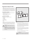
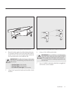
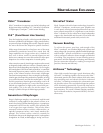
3 Remove the stand/wall-bracket by completely
unscrewing the two large knobs (figure 4).
IMPORTANT! Make sure that the four press fit
washers remain in place, two attached to the
bracket and two attached to the speaker cabinet.
Figure 4. Remove the stand from the speaker.