


25
Nº433 Power Amplifier
Link Controls
Linking Mark Levinson components allows them to share certain
controls. The table below provides a general description of controls
the Nº433 shares with other linked components. Some controls
may not be available for certain component combinations. Other
Mark Levinson components may share additional controls. Refer to
the appropriate documentation for additional information.
Note the following:
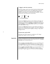
• Linked components must be powered on ONE AT A TIME in the
specific order listed in step 3 (previous page) to ensure proper
functioning of Link controls.
• Link controls must be enabled on the linked digital transport
linking menu, which allows activation and deactivation of
individual Link controls. Refer to the appropriate digital
transport owner’s manual for additional information.
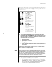
• Some Mark Levinson digital transports accommodate a
maximum of four front-panel display characters. In these cases,
certain input names appear abbreviated on the front-panel
display. For example, an input named Nº326S will appear as
Nº32 on the digital transport front-panel display even though
the input is associated with the Nº 326S.
• The linked preamplifier and power amplifier(s) must be in the
same standby state to allow the linked power amplifier(s) to
enter standby after a power failure.
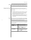
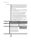
Control
Component
Preamplifier Power Amplifier
Standby Link
Placing the linked preamplifier into standby also
places all other linked power amplifiers into
standby. Taking the linked preamplifier out of
standby also takes all other linked power ampli-
fiers out of standby.
Placing a linked power amplifier into
standby also places all other linked power
amplifiers into standby. Taking a linked
power amplifier out of standby also takes all
other linked power amplifiers out of standby.
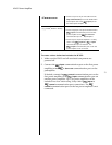
If a linked power amplifier experiences a fault
condition, it will report the fault condition to the
linked preamplifier. If this occurs, the power
amplifier number and fault condition code will
appear on the preamplifier’s front panel display.
The power amplifier number refers to its position
in the slave chain. For example, AMP1 refers to
the first power amplifier in the slave chain. Power
amplifier fault condition codes are described in the
table to the right. Refer to “Extensive Protection”
on page 12 for additional information about fault
conditions.
Code Description
HOT! Iindicates a thermal fault condition.
DCO! Indicates an uncorrectable DC offset.