


18
Mark Levinson
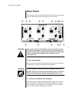
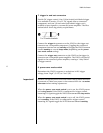
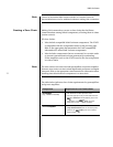
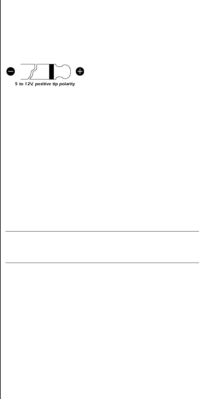
7. trigger in and out connectors
Provide DC trigger control. One 1/8-inch mini-jack labeled trigger
in is available to receive 12 or 5V DC signals from a connected
component, and one 1/8-inch mini-jack labeled trigger out is
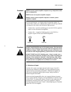
available to pass signals to a connected power amplifier. The illus-
tration below shows tip polarity requirements.
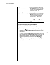
Connect the trigger in connector on the Nº433 to the trigger out
connector on a compatible component. Toggling the connected
component between on and standby will toggle the Nº433 between
on and standby or on and sleep mode (depending on the power
save mode switch setting).
Connect the trigger out connector on the Nº433 to the trigger in
connector on a compatible power amplifier. The Nº433 will pass DC
signals to the connected power amplifier, creating a “daisy-chain”
of trigger control.
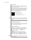
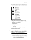
8. power save mode switch
Determines the Nº433’s response to reductions in DC trigger
voltage, from “high” (5-12V) to “low” (0V).
Important!
DO NOT change the power save mode switch setting when the Nº433
is powered on. Make sure power is disconnected from the ~ac mains
connector before making adjustments.
When the power save mode switch is set to on, the Nº433 powers
on in sleep mode. If the Nº433 is configured for trigger control,
incoming DC signals toggle the Nº433 between on and sleep mode.
When the power save mode switch is set to off, the Nº433 powers
on in standby. If the Nº433 is configured for trigger control,
incoming DC signals toggle the Nº433 between on and standby.