


6
ENGLISH
b
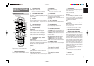
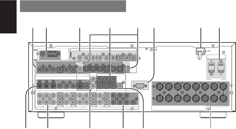
MONITOR OUT
This is a monitor output and each one includes
both composite video and S-video configurations.
When connecting two video monitors or televisions,
be aware that the OSD interface can be used with
both MONITOR OUT connections.
n
RS232C
The RS232C port is to be used in conjunction with
an external controller to control the operation of the
SR6400 by using an external device.
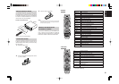
m
Power cable
Connect to an AC power outlet.
SR6400 has to be powered by 120 V AC only.
,
AC OUTLETS
Connect the AC power cables of components such as
a DVD and CD player to these outlets. SWITCHED
and UNSWITCHED outlets are provided.
The one marked SWITCHED provides power only
when the SR6400 is turned on and is useful for
components which you use every time you play
your system.
The one marked UNSWITCHED is always live as
long as the SR6400 is plugged into a live outlet.
A component connected here may be left on
permanently, or may be switched off with via its own
power switch.
Caution:
•
In order to avoid potential turn-off thumps, anything
plugged into these outlets should be powered up
before the SR6400 is turned on.
•
The capacity of this AC outlet is 120W. Do not
connect devices that consume electricity more than
the capacity of these AC outlets. If the total power
consumption of the connected devices exceeds the
capacity, the protection circuit shuts down the
power supply.
.
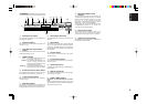
Speaker outputs terminals
Eight terminals are provided for the front (A) left,
front (A) right, front (B) left, front (B) right, front
center, surround left, surround right and surround
back speakers.
⁄0
Subwoofer Output
Connect this jack to the line level input of a powered
subwoofer. If an external subwoofer amplifier is used,
connect this jack to the subwoofer amplifier input. If
you are using two subwoofers, either powered or with
a 2 channel subwoofer amplifier, connect a “Y”
connector to the subwoofer output jack and run one
cable from it to each subwoofer amplifier.
⁄1
6.1 CHANNEL INPUT
By connecting a DVD Audio player, SACD
multichannel player, or other components that has
a multichannel port, you can playback the audio
with 5.1 channel or 6.1 channel outputs.
⁄2
REMOTE CONT. IN/OUT terminals
Connect to a Marantz component equipped with
remote control (RC-5) terminals.
⁄3
AUDIO IN/OUT (CD, TAPE, CD-R, TV,
DVD, VCR1, DSS/VCR2)
These are the analog audio inputs and outputs. There
are 7 audio inputs (4 of which are linked to video
inputs) and 4 audio outputs (2 of which are linked to
video outputs). The audio jacks are nominally labeled
for cassette tape decks, compact disc players, DVD
players and etc.... The audio inputs and outputs
require RCA-type connectors.
⁄4
DIGITAL INPUT (Dig.1 - 6) / OUTPUT
(coaxial, optical)
These are the digital audio inputs and outputs.
There are 3 digital inputs with coaxial jacks, 3 with
optical jacks.
The inputs accept digital audio signals from a
compact disc, LD, DVD, or other digital source
component.
For digital output, there is 1 coaxial output and 1
optical output.
The digital outputs can be connected to MD
recorders, CD recorders, DAT decks, or other
similar components.
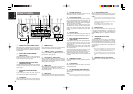
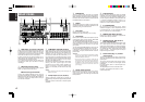
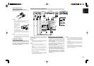
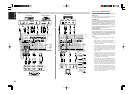
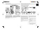
REAR PANEL
c
COMPONENT VIDEO INPUT/OUTPUT
If your DVD player or other device has component
video connectors, be sure to connect them to these
component video connectors on the SR6400. The
SR6400 has two component video input
connectors to obtain the color information (Y, C
B
,
C
R
) directly from the recorded DVD signal or other
video component and one component video output
connector to output it directly into the matrix
decoder of the display device.
By sending the pure DVD component video signal
directly, the DVD signal forgoes the extra
processing that normally would degrade the
image. The result is vastly increased image
quality, with incredibly life like colors and crisp
detail.
Notes:
• This component video output will not display the
OSD menu system.
v
Preamp Outputs (L, R, SL, SR, SB, C)
Jacks for L(front left), R (front right), C (Center), SL
(surround left), SR (surround right) and SB (surround
back).
Use these jacks for connection to external power
amplifiers.
z
VIDEO IN/OUT (TV, DVD, VCR1, DSS/VCR2)
These are the video inputs and outputs. There are
4 video inputs and 2 video outputs and each one
includes both composite video and S-video
configurations. Connect VCRs, DVD players, and
other video components to the video inputs.
S-video sources can be viewed through the S-
video outputs, and composite sources can only be
viewed through the composite output.
The 2 video output channels can be used to be
connected to video tape recorders for making
recordings.
x
FM antenna terminal (75 ohms)
Connect an external FM antenna with a coaxial
cable, or a cable network FM source.
AM antenna and ground terminals
Connect the supplied AM loop antenna. Use the
terminals marked “AM” and “GND”. The supplied
AM loop antenna will provide good AM reception in
most areas. Position the loop antenna until you
hear the best reception.
AUDIO
COMPONENT VIDEO
DIGITAL OUT
DIGITAL IN
OPT. COAX.
ANTENNA
SERIAL NO.
AC IN
AC OUTLETS
120V 60H
Z
SWITCHED
1A 120W MAX
UNSWITCHED
1A 120W MAX
FRONT A
SURROUND
BACK
FRONT B CENTER SURROUND
SPEAKER SYSTEMS
FRONT A OR B, CENTER, SURROUND, SURR. BACK : MINIMUM 6 OHMS
FRONT A AND B : MINIMUM 8 OHMS
LRLRLR
654123
6.1CH
IN
IN OUT
TAPE CDR/MD
OUT SWOUTIN
CD C
SB
SLL
INOUTIN
R
TV DVD DSS/VCR2
RSR
L
VCR1
OUT
IN
RC-5
PRE
OUT
SR SWR
LSLC
SB
DVDTV MONI.
VIDEO
VCR1
OUTOUTIN
DSS/VCR2
OUTIN
VCR1 DSS/VCR2
DVD IN OUT
S-VIDEO
MONI.OUTTV OUTIN
C
B
/
P
B
C
R
/
P
R
C
R
/
P
R
C
R
/
P
R
C
B
/
P
B
C
B
/
P
B
DVD
YY
MONI.OUTDSS/VCR2
Y
FM
(
75
Ω
)
GND AM
RS-232C
bnzx c m ,
⁄0
⁄1
⁄4 ⁄3
v
.⁄2