


12
ENGLISH
AUDIO
COMPONENT VIDEO
DIGITAL OUT
DIGITAL IN
OPT. COAX.
ANTENNA
FRO
SPEAKER SYST
FRONT A OR B
FRONT A AND
R
654123
6.1CH
IN
IN OUT
TAPE CDR/MD
OUT SWOUTIN
CD C
SB
SLL
INOUTIN
R
TV DVD DSS/VCR2
RSR
L
VCR1
OUT
IN
RC-5
PRE
OUT
SR SWR
LSLC
SB
DVDTV MONI.
VIDEO
VCR1
OUTOUTIN
DSS/VCR2
OUTIN
VCR1 DSS/VCR2
DVD IN OUT
S-VIDEO
MONI.OUTTV OUTIN
C
B
/
P
B
C
R
/
P
R
C
R
/
P
R
C
R
/
P
R
C
B
/
P
B
C
B
/
P
B
DVD
YY
MONI.OUTDSS/VCR2
Y
FM
(
75
Ω
)
GND AM
RS-232C
AUDIO
COMPONENT VIDEO
DIGITAL IN
5
OUTIN
R
DVD
L
VCR1
DVD
VIDEO
VCR1
OUTIN
VCR1
DVD
S-VIDEO
MONI.OUTOUTIN
C
B
/
P
B
C
R
/
P
R
C
R
/
P
R
C
B
/
P
B
DVD
YY
MONI.OUT
LR
AUDIO
OUT
DIGITAL
OUT
VIDEO
OUT
S-VIDEO
OUT
S-VIDEO
IN
LR
AUDIO
OUT
AUDIO
IN
LR
VIDEO
OUT IN
S-VIDEO
OUT IN
L R L R LR
YC
B
/
P
B
C
R
/
P
R
COMPONENT
VIDEO OUT
YC
B
/
P
B
C
R
/
P
R
COMPONENT
VIDEO IN
L R L R
L R
AUDIO
COMPONENT VIDEO
DIGITAL OUT
DIGITAL IN
OPT. COAX.
ANTENNA
SPEA
FRON
FRON
654123
6.1CH
IN
IN OUT
TAPE CDR/MD
OUT SWOUTIN
CD C
SB
SLL
INOUTIN
R
TV DVD DSS/VCR2
RSR
L
VCR1
OUT
IN
RC-5
PRE
OUT
SR SWR
LSLC
SB
DVDTV MONI.
VIDEO
VCR1
OUTOUTIN
DSS/VCR2
OUTIN
VCR1 DSS/VCR2
DVD IN OUT
S-VIDEO
MONI.OUTTV OUTIN
C
B
/
P
B
C
R
/
P
R
C
R
/
P
R
C
R
/
P
R
C
B
/
P
B
C
B
/
P
B
DVD
YY
MONI.OUTDSS/VCR2
Y
FM
(
75
Ω
)
GND AM
RS-232C
AUDIO
DIGITAL IN
2
IN
R
TV DSS/VCR2
L
TV MONI.
VIDEO
OUTIN
DSS/VCR2
DSS/VCR2
IN
S-VIDEO
MONI.OUT
LR
AUDIO
OUT
DIGITAL
OUT
VIDEO
OUT
S-VIDEO
OUT
AUDIO
OUT
LR
VIDEO
OUT
S-VIDEO
IN
VIDEO
IN
LR
L R
L R
L R
L R
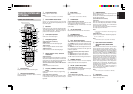
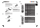
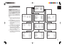
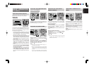
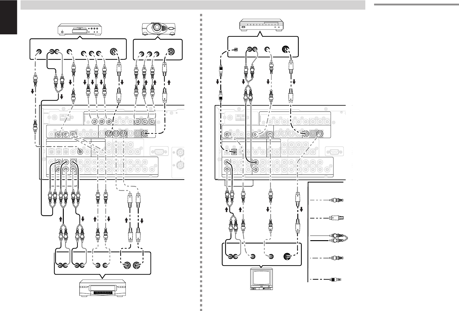
CONNECTING VIDEO COMPONENTS
ANALOG AUDIO
VIDEO
S-VIDEO
DVD PLAYER
VIDEO PROJECTOR
SATELLITE TUNER
DIGITAL AUDIO
(COAXIAL)
VCR
TV
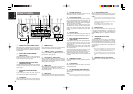
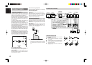
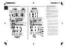
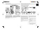
VIDEO, S-VIDEO , COMPONENT JACKS
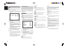
There are 3 types of video jacks on the rear panel.
VIDEO jack
The video signal for the VIDEO jacks is the
conventional composite video signal.
S-VIDEO jack
The video signal is separated into luminance (Y)
and color (C) signals for the S-VIDEO jack. The S-
VIDEO signals enables high-quality color
reproduction. If your video component has an S-
VIDEO output, we recommend to use it. Connect
the S-VIDEO output jack on your video component
to the S-VIDEO input jack on this unit.
Component jack
Make component video connections to a TV or
monitor with component inputs to produce higher
quality video images. Use a component video cable
or 3 video cords to connect the component video
out jacks on the SR6400 to the monitor.
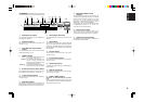
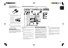
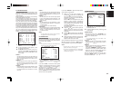
Notes:
•
Be sure to connect the left and right audio channels
properly.
Red connectors are for the R (right) channel, and
white connectors are the for L (left) channel.
• Be sure to connect the inputs and outputs of the
video signals properly.
• If you connect the S-VIDEO or component signal
to the S-VIDEO or component jack on this unit, it
is not necessary to connect the conventional video
signal to the VIDEO (composite) jack. If you use
both video inputs, this unit gives priority to the S-
VIDEO signal.
• Each type of video jack works independently.
Signals input to the VIDEO (composite) and S-
VIDEO jacks or component are output to the
corresponding VIDEO (composite) and S-VIDEO
or component jacks, respectively.
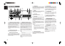
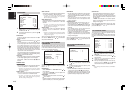
•
This unit has the “TV-AUTO ON/OFF” function to
turn the TV ON or OFF automatically, by sensing
the incoming video signal from the VIDEO jacks.
• You may need to setup the digital audio output
format of your DVD player, or other digital source
components. Refer to the instructions of the each
component connected to the digital input jacks.
• There is no Dolby Digital RF input jack. Please
use an external RF demodulator with a Dolby
Digital decoder to connect a video disc player
which has a Dolby Digital RF output jack to the
digital input jack on this unit.
DIGITAL AUDIO
(OPTICAL)