


14
ENGLISH
DIGITAL
DIGITAL
IN
IN
OUT
OUT
DIG-1 IN
DIG-1 IN
DIG-2 IN
DIG-2 IN
DIG.OUT
DIG.OUT
OPT
OPT
DIG-4 IN
DIG-4 IN
DIG-3 IN
DIG-3 IN
DIG.OUT
DIG.OUT
COAX
COAX
SURROUND
SURROUND
BACK
BACK
R
R
SURROUND
SURROUND
L
L
L
L
FRONT
FRONT
CENTER
CENTER
R
R
VIDEO
VIDEO
S-VIDEO
S-VIDEO
IN
IN
OUT
OUT
IN
IN
OUT
OUT
IN
IN
OUT
OUT
IN
IN
IN
IN
IN
IN
OUT
OUT
DSS
DSS
/
/
VCR2
VCR2
VCR1
VCR1
DVD
DVD
AUDIO
AUDIO
TV
TV
TAPE
TAPE
CD
CD
CDR
CDR
/
/
MD
MD
SUB
SUB
WOOFER
WOOFER
CENTER
CENTER
CENTER
CENTER
FRONT
FRONT
FRONT
FRONT
SURROUND
SURROUND
SURR.
SURR.
BACK
BACK
SURROUND
SURROUND
SUB
SUB
WOOFER
WOOFER
SURR.
SURR.
BACK
BACK
6.1CH INPUT
6.1CH INPUT
L
L
R
R
IN
IN
MONITOR
MONITOR
OUT
OUT
VCR1 OUT
VCR1 OUT
VCR1 IN
VCR1 IN
DVD IN
DVD IN
L
L
R
R
IN
IN
IN
IN
OUT
OUT
OUT
OUT
PRE OUT
PRE OUT
OUT
OUT
MONITOR
MONITOR
IN
IN
TV
TV
DSS
DSS
/
/
VCR2
VCR2
DVD
DVD
VCR1
VCR1
IN
IN
GND
GND
AM
AM
FM
FM
ANTENNA
ANTENNA
(
(
75
75
Ω
Ω
)
)
REMOTE
REMOTE
CONTROL
CONTROL
MODEL NO. SR4300
SWITCHED 100W MAX
SWITCHED 100W MAX
SPEAKER SYSTEMS
SPEAKER SYSTEMS
AC OUTLET
AC OUTLET
DIGITAL
DIGITAL
DIG-1 IN
DIG-1 IN
DIG.OUT
DIG.OUT
OPT
OPT
DIG-4 IN
DIG-4 IN
IN
IN
OUT
OUT
IN
IN
OUT
OUT
IN
IN
AUDIO
AUDIO
TAPE
TAPE
CD
CD
CDR
CDR
/
/
MD
MD
L
L
R
R
OUT IN
L
R
L
R
OUT
L
R
L R
L R
L R
RLLR RL
OUT IN
L
R
L
R
DIGITAL
OUTPUT
DIGITAL
OUTPUT
DIGITAL
INPUT
R L
L R L R
RL
L R
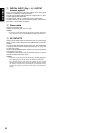
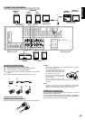
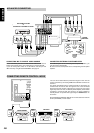
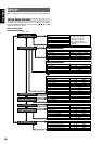
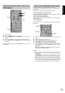
CONNECTING AUDIO COMPONENTS
The output audio signal from the TAPE OUT jack and the CD-R/MD
OUT jack is the sound source currently selected.
Caution:
• Do not connect this unit and other components to mains power
until all connections between components have been
completed.
Notes:
• Insert all plugs and connectors securely. Incomplete
connections may make noise.
• Be sure to connect the left and right channels properly.
Red connectors are for the R(right) channel, and white
connectors are for the L(left) channel.
• Be sure to connect input and output properly.
• Refer to the instructions for each component that is connected
with this unit.
• Do not bind audio/video connection cables with power cords
and speaker cables will result in generating hum or other noise.
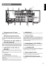
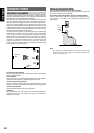
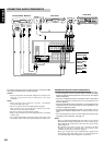
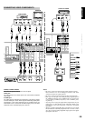
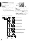
CONNECTING DIGITAL AUDIO COMPONENTS
• There are four digital inputs, two coaxial jacks and two optical jacks,
on the rear panel. You can use these jacks to input PCM, Dolby
Digital and DTS bitstream signals from a CD, DVD, or other digital
source components.
• There are one digital output with coaxial jack and one with optical
jack on the rear panel. These jacks can be connected to CD
recorder, MD deck.
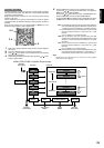
• Setup the digital audio format of DVD player, or other digital source
component. Refer to the instructions for each component to be
connected to digital input jacks.
• Use fiber optical cables(optical) for DIG-1,2 input jacks. Use 75
ohms coaxial cables(for digital audio or video) for DIG-3,4 input
jacks.
• You can designate the input for each digital input/output jacks
according to your component. See page 19.
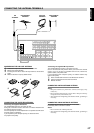
Notes:
• There is no Dolby Digital RF input jack. Please use an external
RF demodulator Dolby Digital decoder when connecting the
Dolby Digital RF output jack of the video disc player to the
digital input jack.
• The digital signal jacks on this unit conform to the EIA
standard. If you use a cable that does not conform to this
standard, this unit may not function properly.
• Each type of audio jack works independently. Signals input
through the digital and analog jacks are output through the
corresponding digital and analog jacks, respectively.
CD RECORDER / MD DECK
CD PLAYER
TAPE DECK
ANALOG AUDIO
DIGITAL AUDIO
(COAXIAL)
DIGITAL AUDIO
(OPTICAL)