


4
English
English
FOREWORD
This section must be read before any connection is made to the
mains supply.
WARNINGS
Do not expose the equipment to rain or moisture.
Do not remove the cover from the equipment.
Do not push anything inside the equipment through the
ventilation holes.
Do not handle the mains lead with wet hands.
EQUIPMENT MAINS WORKING SETTING
Your Marantz product complies with the household power and
safety requirements in your area.
“N”or “UK” Version product can be powered by 230 V AC only.
IMPORTANT:
This apparatus is fitted with an approved moulded 13 Amp plug.
To change a fuse in this type of plug proceed as follows:
1. Remove fuse cover and fuse.
2. Fix new fuse which should be a BS1362 5A, A.S.T.A. or BSI
approved type.
3. Refit the fuse cover.
If the fitted plug is not suitable for your socket outlets, it should be
cut off and an appropriate plug fitted in its place.
If the mains plug contains a fuse, this should have a value of 5A.
If a plug without a fuse is used, the fuse at the distribution board
should not be greater than 5A.
NOTE: The severed plug must be destroyed to avoid a possible
shock hazard should it be inserted into a 13A socket
elsewhere.
HOW TO CONNECT A PLUG
The wires in the mains lead are coloured in accordance with the
following code:
BLUE—”NEUTRAL” (“N”)
BROWN—”LIVE” (“L”)
1. The BLUE wire must be connected to the terminal which is
marked with the letter “N” or coloured BLACK.
2. The BROWN wire must be connected to the terminal which is
marked with the letter “L” or coloured RED.
3. Do not connect either wires to the earth terminal in the plug
which is marked by the letter “E” or by the safety earth symbol
or coloured green or green-and-yellow.
Before replacing the plug cover, make certain that the cord grip
is clamped over the sheath of the lead — not simply over the two
wires.
COPYRIGHT
Recording and playback of any material may require consent. For
further information refer to the following:
— Copyright Act 1956
— Dramatic and Musical Performers Act 1958
— Performers Protection Acts 1963 and 1972
— any subsequent statutory enactments and orders
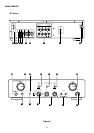
ABOUT THIS USER GUIDE
Refer to the Figures on the pages at the rear of this user guide.
The callout numbers on the Figures correspond to those found in
the text. All references to the connections and controls that are
printed in BOLD type are as they appear on the unit.
PRECAUTIONS
The following precautions should be taken when operating the
equipment.
GENERAL PRECAUTIONS
When setting the equipment ensure that:
— the ventilation holes are not covered
— air is allowed to circulate freely around the equipment
— it is on a vibration free surface
— it will not be exposed to interference from an external source
— it will not be exposed to excessive heat, cold, moisture or dust
— it will not be exposed to direct sunlight
— it will not be exposed to electrostatic discharges
In addition, never place heavy objects on the equipment.
If a foreign body or water does enter the equipment, contact your
nearest dealer or service center.
Do not pull out the plug by pulling on the mains lead, hold the plug.
It is advisable when leaving the house, or during a thunder-storm,
to disconnect the equipment from the mains supply.
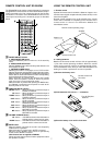
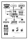
CONNECTIONS (Figure 1)
CONNECTION OF TUNER
Connect the output jacks of your stereo tuner to the TUNER jacks
of this unit.
CONNECTION OF COMPACT DISC PLAYER
Connect the output jacks of your CD player to the CD jacks of this
unit.
CONNECTION OF TURNTABLE
Connect the L (Left) output cord of the turntable to the “L”
PHONO jack of this unit, and connect the R (Right) output cord
to the “R” PHONO jack. Also be sure to connect the turntable’s
grounding wire to the GND jack of this unit. The GND jack does
not have to be connected if the turntable is not provided with a
grounding wire.
CONNECTION OF MD/TAPE DECK
Connect the IN (recording input) jacks of the tape deck to the
TAPE OUT jacks of this unit, and connect the OUT (playback
output) jacks of the tape deck to the MD/TAPE IN jacks of this unit.
CONNECTION OF CD recorder
Connect the IN (recording input) jacks of the CD recorder to the
CD-R OUT jacks of this unit, and connect the OUT (playback
output) jacks of the CD recorder to the CD-R IN jacks of this unit.
CONNECTION OF SPEAKER SYSTEMS
This unit is equipped with two sets of SPEAKER SYSTEM
terminals––SYSTEM 1 terminals and SYSTEM 2 terminals.
Usually connect your speaker system to the SYSTEM 1 terminals.
¡ The speakers in the speaker system should have an imped-
ance between 8 and 16 ohms. If speakers with an impedance
of less than 8 ohms are connected, the protection circuitry may
be activated during play.
¡ Connect the Right channel speaker to the R terminals, and the
Left channel speaker to the L terminals.
¡ The output terminals have positive (+: Red) and negative
(–: Black) polarity, and each speaker also has the same
polarity (+ and –). When connecting the speaker, be sure to
connect the terminals with the same polarity (+ with +, –
with –).