


10
AV2
CVI
AV1
24
Front
L/Mono
Monitor out
VIDEO
S-VIDEO
AV1 in
Y
Pb
Pr
AV2 in
AUDIO
R
COMPONENT VIDEO INPUT
AUDIO OUT
L R
S-VIDEO
OUT
ANT/CABLE
OUT
VIDEO
OUT
SVHS
1
2
1
2
3
5
123
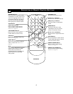
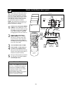
POWER
CH
CH
VOL
VOL
STATUS
EXIT
SLEEP
MUTE
SMART
PICTURE SOUND
SURF
A/CH
45
6
789
0
CC
MENU
MAGNAVOX
4
T
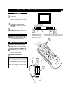
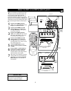
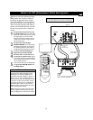
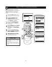
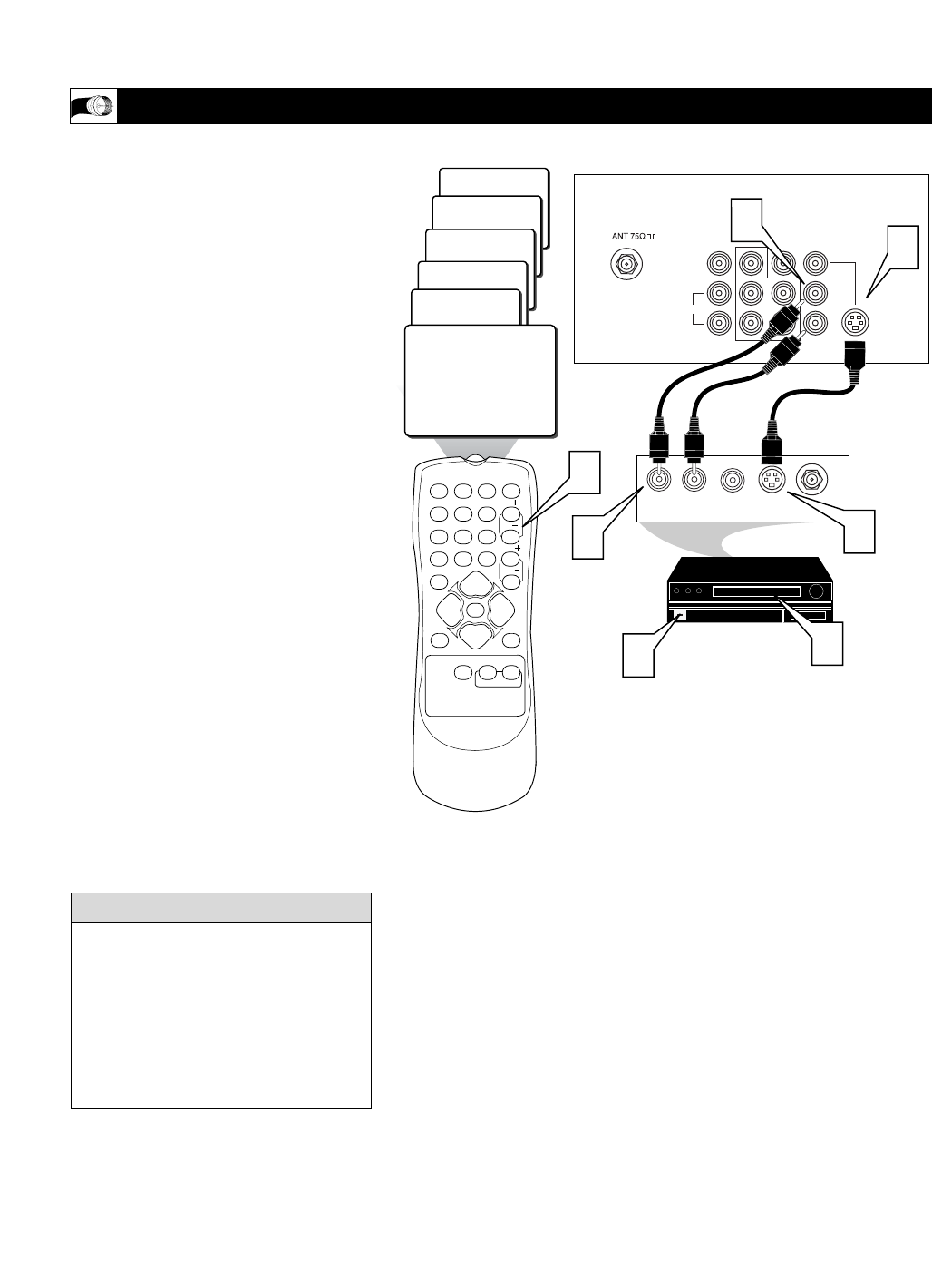
he S(uper)-Video connection on the rear of
the TV can provide you with better picture
detail and clarity for the playback of accessory
sources such as DBS (digital broadcast satellite),
DVD (digital video discs), video games, and S-
VHS VCR (video cassette recorder) tapes than
the normal antenna picture connections.
NOTE: The accessory device must have an S-
VIDEO OUT(put) jack in order for you to com-
plete the connection on this page.
1
Connect one end of the S-VIDEO
CABLE to the S-VIDEO jack on the
back of the TV. Then connect one end
the AUDIO (red and white) CABLES
to the AV2 in AUDIO L and R (left
and right) jacks on the rear of the TV.
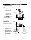
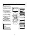
2
Connect other end of the S-
VIDEO CABLE to the S-VIDEO
OUT jack on the back of the VCR.
Then connect the other ends of the
AUDIO (red and white) CABLES to
the AUDIO (left and right) OUT jacks
on the rear of the VCR.
3
Turn the VCR and the TV ON.
4
Press the CH + or CH- buttons to
set the TV to its SVHS2 channel.
(Go to your lowest channel,for example
channel 1, then change channels down to
find the correct source channel.)
5
Now your ready to place a prerecord-
ed video tape in the VCR and press
the PLAY ᮣ button
.
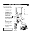
USING THE S-VIDEO INPUT JACKS
The S-VIDEO and VIDEO AV2 in(puts) are
in parallel. The S-VIDEO input is dominant
when in use. If separate video signals are
connected to the S-VIDEO and VIDEO
AV2 in(puts), the signal from the VIDEO
AV2 in(puts) will not be usable.
Audio and S-Video cables are not supplied
with the TV, but are available from
Magnavox or electronics retailers.
HELPFUL HINT
Audio Cable
(Red and White)
VCR
(Equipped with
S-Video Jacks)
S-Video Cable
Back of VCR
Back of TV