


8
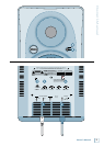
HR84 MK
HR824 MK2
REAR PANEL DESCRIPTION
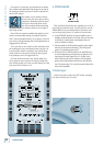
. INPUT SENSITIVITY
AUTO
STANDBY
ON
ON
ACOUSTIC SPACE LOW FREQ HIGH FREQ. POWER MODE
NORMALOFF
HALFQUARTER
WHOLE
(
NORMAL
)
37Hz80Hz
0
(
NORMAL
)
–
2dB
+
2dB
47Hz
INPUT
SENSITIVITY
LOW CUT
–
10dB
(
NORMAL
)
THX = NORMAL
The HR824 MK2 expects a line-level signal at its input
connectors.
• The reference sensitivity is –7.5 dBu=100 dB SPL at
one meter (39 inches) with the INPUT SENSITIVITY
control set to its NORMAL position (in other words,
wide open).
• The HR824 MK2 is designed to operate with a +4 dBu
signal when the INPUT SENSITIVITY control is in the
NORMAL position.
• Refer to the QUICK START section on page 4 for the
level-setting procedure.
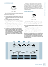
. ACOUSTIC SPACE
AUTO
STANDBY
ON
ON
ACOUSTIC SPACE LOW FREQ HIGH FREQ. POWER MODE
NORMALOFF
HALFQUARTER
WHOLE
(
NORMAL
)
37Hz80Hz
0
(
NORMAL
)
–
2dB
+
2dB
47Hz
INPUT
SENSITIVITY
LOW CUT
–
10dB
(
NORMAL
)
THX = WHOLE (NORMAL)
This is a three-way switch that adjusts the low-fre-
quency response of the monitors to compensate for their
placement in the room. See page 5 for an overview of
the rear panel.
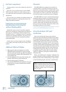
• If you place the HR824 MK2 monitors against a wall
(half space [3B]), set the ACOUSTIC SPACE switch
to the “B” position. This activates a shelving filter to
reduce the low-frequency output by 2 dB to compensate
for the half-space placement.
• If you place the monitors into the corners of your
room (quarter space [3A]), the low-frequency output
approximately doubles from what it is in half space.
Set the ACOUSTIC SPACE switch to the “A” position to
reduce the low-frequency output by 4 dB to compensate
for the quarter-space placement.
• If you use the HR824 MK2s free-standing, away from
walls and corners (whole space [3C]), set the ACOUS-
TIC SPACE switch to the “C” position (NORMAL).
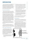
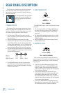
This is where you connect your signal to the monitor,
and make adjustments to the frequency response of
the speakers to match the monitor’s location and your
room’s environment.
For THX applications, the rear panel
switches and controls should be set
to the THX positions as indicated in
this section.
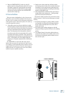
1. SIGNAL INPUTS
The location of the signal input jacks makes the con-
nectors exit down and not straight out the back of the
enclosure. This flush-mount design allows you to place
the monitor right up against the wall if desired.
• The XLR female, TRS female (balanced), and RCA
female (unbalanced) input connectors are provided for
user convenience.
• Don’t connect more than one source to the jacks.
• Unbalanced TS (tip-sleeve) lines can be accommodated
via the TRS jack. Make sure the cable terminates with
a TS plug (like a guitar plug), or if it’s a TRS plug (such
as a headphone plug), make sure the ring is tied to the
sleeve and that the plug is fully inserted into the jack.
• The XLR and TRS input connectors accept balanced or
unbalanced signals. The connectors are wired as follows
(per the AES/IEC standard):
XLR TRS RCA
Hot (+) Pin 2 Tip Tip
Cold (–) Pin 3 Ring —
Shield (Ground) Pin 1 Shield Shield
• The HR824 MK2s can be used with a home receiver
even if the receiver lacks a preamp output by using a
speaker-level to line-level signal attenuator. (See page
13 for more information.)