


10
Amplifier Rear Panel Function ControlsAmplifier Rear Panel Function Controls
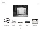
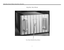
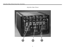
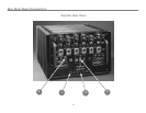
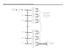
BBefore attempting any system interconnection, please familiarize yourself with the rear panel controls of the MC-6 Multi-Channel Power Amplifier.
The descriptions below refer to the illustrations above.
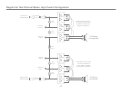
11 INPUT LINK SWITCHES FOR CHANNELS 1, 2, 3, 4, 5, AND 6:INPUT LINK SWITCHES FOR CHANNELS 1, 2, 3, 4, 5, AND 6: These
switches allow the individual channels of the MC-6 to be linked in
parallel to create single channels of great power and current
capability. THE CORRECT SWITCHES MUST BE SWITCHED ON WHEN
THE APPROPRIATE JUMPERS ARE PLACED ACROSS THE
CORRESPONDING OUTPUT TERMINALS.
+ WARNING:WARNING: IF ANY OUTPUT TERMINALS ARE JUMPERED
TOGETHER, THE CORRESPONDING INPUTS MUST BE LINKED VIA THE
INPUT LINK SWITCHES! FAILURE TO OBSERVE THIS PROCEDURE WHEN
OPERATING THE AMPLIFIER WILL DAMAGE THE INTERNAL CIRCUITRY
AND WILL VOID THE WARRANTY!
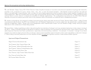
BE SURE TO STRICTLY FOLLOW THE APPLICABLE CHANNEL
CONFIGURATIONS AS SHOWN IN THE “SIGNAL CONNECTIONS
CONTENTS DIRECTORY” ON PAGE 14 OF THIS MANUAL.
22 INPUT SELECT SWITCH FOR CHANNELS 1, 2, 3, 4, 5, AND 6:INPUT SELECT SWITCH FOR CHANNELS 1, 2, 3, 4, 5, AND 6: This
switch selects either the unbalanced RCA inputs or the balanced
XLR inputs. This switch can be switched while the amplifier is
operational and playing music. Note: Note: When the RCA position is
selected, pin 2 of the XLR is shorted to pin 1 (signal ground).
33 REMOTE: REMOTE: A remote connector (5-Pin DIN) is provided on the rear
panel for remotely switching the amplifier between operational
and standby modes. The pin connections on this connector
parallel the electrical contacts of the FRONT PANEL
STANDBY/POWER button and lamp. Contact your dealer or the
Jeff Rowland Design Group factory for further information about
this feature.