


9
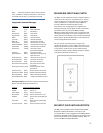
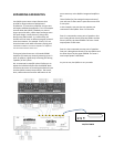
R+ R- L- L+
8 - BROWN - REDUNDANT TIA/EIA - T568A
7 - WHITE/BROWN - REDUNDANT
6 - ORANGE - INFRARED
5 - WHITE/BLUE - COMMON / GOUND / EARTH
4 - BLUE - DC +12V
3 - ORANGE/WHITE - REDUNDANT
2 - GREEN - SYSTEM DATA
1 - WHITE/GREEN - SYSTEM CLOCK
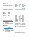
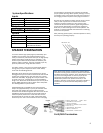
System Specifications
Inputs
Direct Inputs
4 gold stereo RCA
Balanced Inputs
4 RJ45 from BIX or BIB
Control
1 RS232 nine pin port
Infrared
Not implemented
Outputs
Stereo amplifiers
4 x 50 watts 4-16 ohms
Direct Outputs
4 controlled gold stereo RCA
System
Frequency Response
20 Hz to 20 kHz
Operating Temp.
-20°C to 45°C (
Dimensions
89 x 53 x 333 mm (3.5 x 2 x 13.2ʺ)
Weight
820 g (1.81 lbs.)
Power
DC 24 V center pin +
100-240 VAC 50-60 Hz
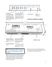
SPEAKER TERMINATION
To ensure that the high quality signals produced by your
amplifier are carried to your speakers without loss of
clarity or resolution, Knoll advises that you use high-quality
speaker wire. Many brands of wire are available — the
choice may be influenced by the distance between your
speakers and the amplifier, the type of speakers you use,
personal preferences, along with other factors.
For safety reasons, if any wires are placed inside walls or
ceilings, they may be required to be fire rated. Always
check with local building officials.
Regardless of the brand or type of speaker wire chosen,
we suggest that you use a wire constructed of multi-strand
copper with a gauge of 16 or less (the lower the number,
the thicker the cable). 16 gauge wire may be used for runs
up to 33’ (10 m). 14 -12 gauge wire is recommended for
longer runs. We do not recommend that you use any wires
with an AWG equivalent of 18 or higher due to the power
loss and degradation in performance.
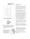
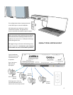
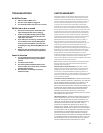
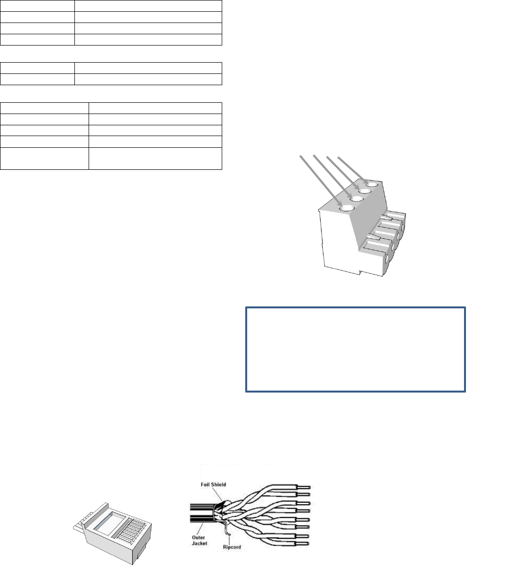
A detachable plug is provided for each stereo channel
output. Strip approximately ¼” (6 mm) of insulation from
the end of each speaker wire and carefully twist the
strands of each conductor together. Be sure not to cut the
individual strands or twist them off. All strands must be
used for optimal performance. Insert the wire into the
plug and screw the screws very tight. Inspect that there
are no stray wire “hairs” that can short circuit in the plug.
Correct polarity connections are important to maintain
proper speaker phasing. When speaker phasing is correct,
all speakers move in and out at the same time preserving
the imaging and bass response of the program material.
Run the wires to speaker locations. Do not coil any excess
cable, as this may become an inductor that creates
frequency response variations in your system. Lastly,
connect the wires to the speakers, again being aware of
proper polarity. Remember to connect the negative or
black wire, to the matching terminal on the speaker. The
positive or red wire should be connected to the matching
terminal on the speaker.
After powering up the system, check the speakers to verify
that they are operating properly.
Note: While most speaker manufacturers follow industry
convention of using red terminals for positive connections
and black terminals for negative, some manufacturers may
vary from this configuration. To ensure proper phase
connections and optimal performance, consult the
identification plate on our speaker terminals, or the
speaker’s manual to verify polarity. Contact the speaker’s
manufacturer if you do not know the polarity of your
speakers.
Cat 5/RJ45 Termination
Pin 8
Pin 1