


XD-8550/XD-6000 (En/T)
6
Preparation sectionBasic sectionApplication sectionKnowledge sections
R L
+
−
+
−
SPEAKERS
( 6 - 16Ω )
SUPER
WOOFER
PRE OUT
CONNECT WITH C-H5 OR C-H6 OR C-H7
CONNECT WITH A-H5
R
L
GND
AM
ANTENNA
MD AUX
INPUT
REC
OUT
PLAY
IN
FM 75Ω
OPTICAL
CONNECT WITH
C-H5 OR C-H6 OR C-H7
AND
X-H5 OR DM-H5
DIGITAL
OUTPUT
CONNECT WITH
DP-H5 OR DP-MH5
SYSTEM
CONROL
−
+
R L
+
−
+
−
SPEAKERS
( 6 - 16 Ω )
GND
AM
FM 75Ω
55
11
33
22
44
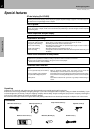
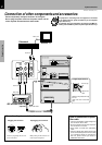
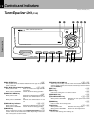
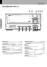
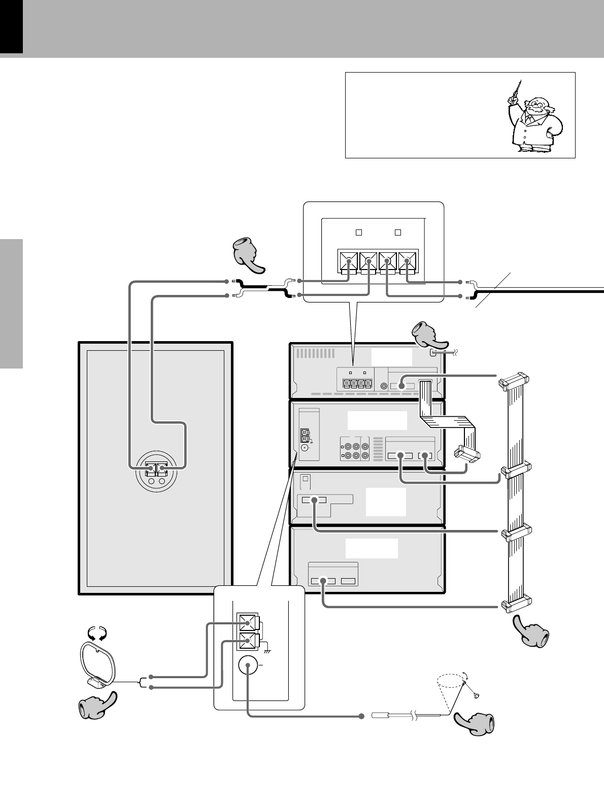
System connection
This is the connection method for system and accessories.
Please look carefully at the illustration and connect cor-
rectly in the order of the numbers.
With certain models, the positions of the connectors, jacks
and terminals may differ from the following illustration but
their designs are the same as those illustrated below: With
such models, please make connections by referring to the
following illustration.
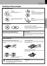
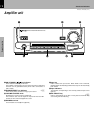
Connection of the System Accessories
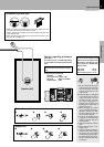
Malfunction of microcomputer
If operation is not possible or erro-
neous display appears even though
all connections have been made
properly, reset the microcomputer
referring to “In case of difficulty”.
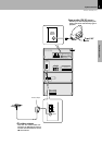
∏
The supplied antenna is for indoor use. Place it as far as
possible from the main system, TV set, speaker cords and
power cord, and set it to a direction which provides the
best reception.
AM loop antenna
Speaker (right)
To wall AC outlet
Power cord
Speaker cord
Red
Black
FM indoor antenna
The accessory antenna is for temporary indoor use only. For sta-
ble signal reception we recommend using an outdoor antenna.
Remove the indoor antenna if you connect one outdoors.
1Locate the position
providing good recep-
tion condition.
2Fix the antenna.
Parallel cord
Amplifier
A-H5
Tuner/Equalizer
C-H6 or C-H5
Cassette deck
X-H5
CD player
DP-H5 or
DP-MH5