


8
XD SERIES (En)
Preparation
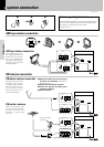
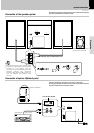
system connection
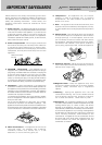
Caution regarding placement
To maintain proper ventilation, be sure to leave a space around
the unit (from the largest outer dimensions including projec-
tions) equal to, or greater than, shown below.
Rear panel: 10 cm
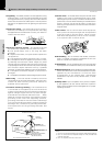
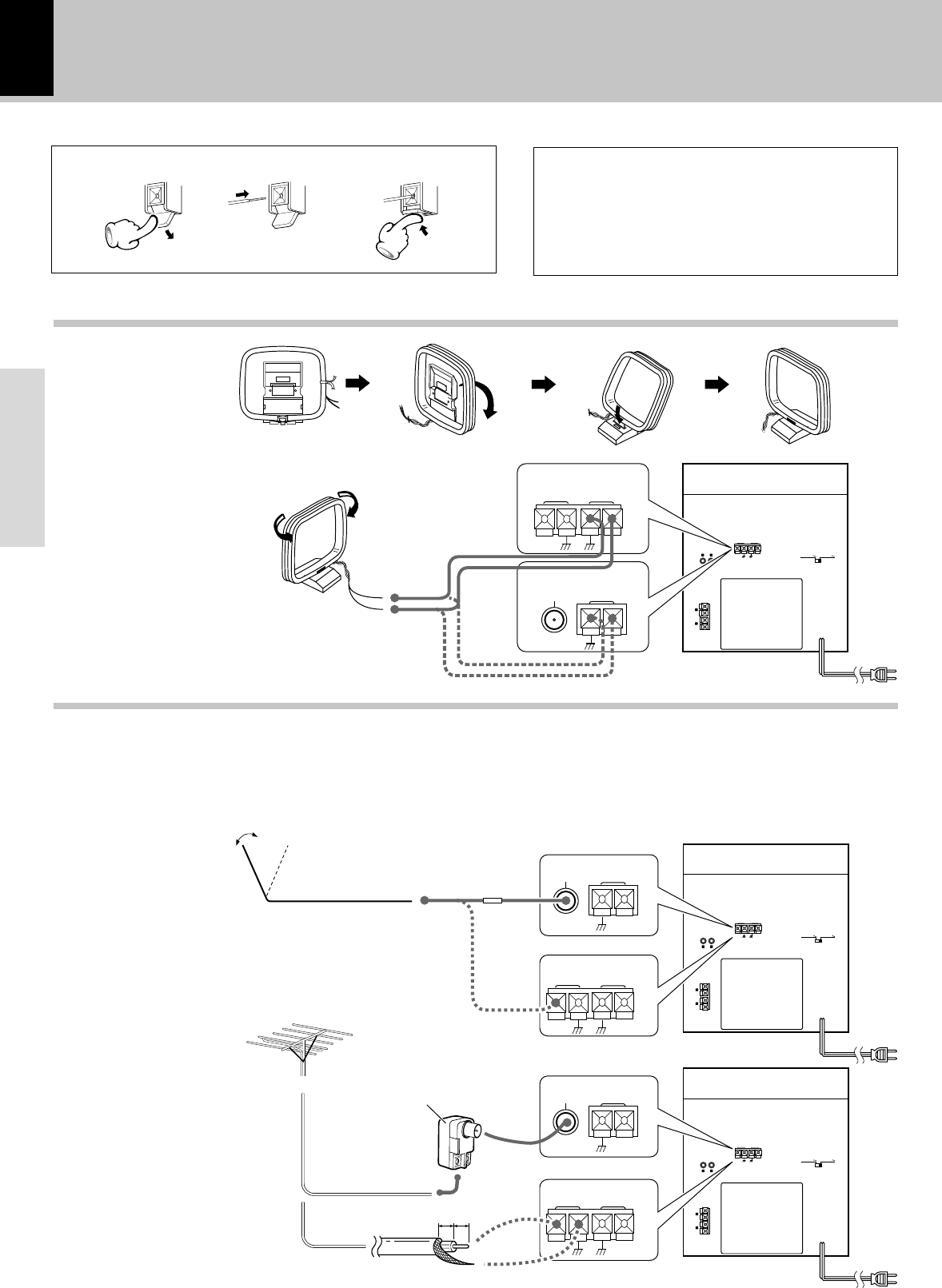
AM loop antenna connection
The supplied antenna is for
indoor use. Place it as far as
possible from the main sys-
tem, TV set, speaker cords
and power cord, and set it to
a direction which provides
the best reception.
FM indoor antenna connection
The accessory antenna is for
temporary indoor use only.
For stable signal reception
we recommend using an
outdoor antenna. Remove
the indoor antenna if you
connect one outdoors.
123
AM loop antenna connection
FM antenna connection
AUX INPUT
R
L
–
+
+
–
SPEAKERS
(6–16 Ω)
FM 75 Ω
AM
ANTENNA
GND
AC 220–240VAC 110–120V
SUPER
WOOFER
PRE OUT
FM 75 Ω
AM
ANTENNA
GND
FM 75 Ω
AM
ANTENNA
GND
R L
R L
AUX
INPUT
R
L
–
+
+
–
SPEAKERS
(6–16 Ω)
FM 75 Ω
AM
ANTENNA
GND
AC 220–240VAC 110–120V
R L
AUX
INPUT
R
L
–
+
+
–
SPEAKERS
(6–16 Ω)
FM 75 Ω
AM
ANTENNA
GND
AC 220–240VAC 110–120V
FM 75 Ω
AM
ANTENNA
GND
FM 75 Ω
AM
ANTENNA
GND
FM 75 Ω
AM
ANTENNA
GND
FM 75 Ω
AM
ANTENNA
GND
10mm 10mm
1 Strip the coating from the tip of cord
and twist the conductor. (Except for
Europe and U.K.)
2 Connect to the antenna terminal.
3 Locate the position providing good
reception condition.
4 Fix the antenna.
FM outdoor antenna
Lead the 75Ω coaxial cable
connected to the FM outdoor
antenna into the room and
connect it to the FM 75Ω
termimal.
Antenna adapter
(optional)