8
EN
Setting up the system
Input mode settings
CD/DVD, VIDEO 2, VIDEO 3 and DVD/6CH inputs each include jacks
for digital audio input and analog audio input.
The initial factory settings for audio signal playback for CD/DVD,
DVD/6CH, VIDEO 2 and VIDEO 3 are FULL AUTO.
After completing connections and turning on the receiver, follow the
steps below.
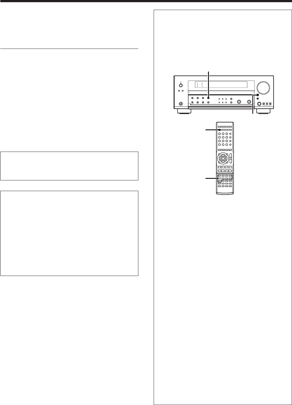
INPUT MODE
INPUT SELECTOR
Input Selector
keys
INPUT MODE
1 Use the INPUT SELECTOR key or Input Selector keys to select
CD/DVD, VIDEO 2, VIDEO 3 or DVD/6CH.
2 Press the INPUT MODE key.
Each press switches the setting as follows:
In DTS play mode
1 FULL AUTO (digital input, analog input)
2 DIGITAL MANUAL (digital input)
In CD/DVD, VIDEO 2, VIDEO 3 or DVD/6CH play mode
1 FULL AUTO (digital input, analog input)
2 DIGITAL MANUAL (digital input)
3 6CH INPUT (DVD/6CH input only)
4 ANALOG (analog input)
Auto detect:
In FULL AUTO mode ("AUTO DETECT" indicator lights up), the
receiver detects the digital or analog input signals automatically.
The receiver will select the input mode and listening mode auto-
matically during playback to match the type of input signal (Dolby
Digital, PCM, DTS) and the speaker setting. •
The "DIGITAL" indicator lights up when a digital signal is
detected. The "DIGITAL" indicator is extinguished when no
digital signal is detected.
Fixed to digital input:
Select this mode if you want to keep the decoding condition (Dolby
Digital, DTS, PCM, etc.) in the current listen mode.
When DIGITAL MANUAL mode is selected, the set listen modes
may be changed automatically depending on the input signal. •
Fixed to analog input:
Select this setting to play analog signals from a VCR, etc.
If the INPUT MODE key is pressed quickly, sound may not be
produced. Press the INPUT MODE key again.
Memory back up function
Please note that the following items will be deleted from the unit's
memory if the power cord is disconnected from the AC outlet for
approximately 1 day.
•Power mode
•Input selector settings
•Speaker ON/OFF
•Volume level
•BASS, TREBLE, INPUT level
• TONE ON/OFF
• LOUDNESS ON/OFF
•Dimmer level
•Listen mode setting
•Speaker settings
• Distance setting
•Input mode setting
•Sound mode settings
•Broadcast band
•Frequency setting
•Preset stations
•Tuning mode
•ACTIVE EQ mode
•GAME mode setting
Make connections as shown in the following pages.
When connecting the related system components, be sure
to refer to the instruction manuals supplied with the
components you are connecting.
Do not connect the power cord to a wall outlet until all
connections are completed.
Notes
1.
Be sure to insert all connection cords securely. If their connections are
imperfect, sound may not be produced or there will be noise inference.
2.Be sure to remove the power cord from the AC outlet before plugging
or unplugging any connection cords. Plugging/unplugging connection
cords without disconnecting the power cord can cause malfunctions
and may damage the unit.
3.Do not connect power cords from components whose power
consumption is larger than what is indicated on the AC outlet at the
rear of this unit.
Analog connections
Audio connections are made using RCA pin cords. These cables transfer
stereo audio signal in an “analog” form. This means the audio signal
corresponds to the actual audio of two channels. These cables usually
have 2 plugs on each end, one red for the right channel and one white for
the left channel. These cables are usually packed together with the
source unit, or are available at your local electronics retailer.
Microcomputer malfunction
If operation is not possible or an erroneous display appears, even
though all connections have been made properly, reset the
microcomputer referring to “In case of difficulty”. t
2/9/05, 10:18 AM8


