


9
Preparation section
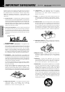
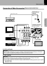
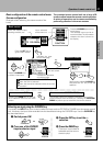
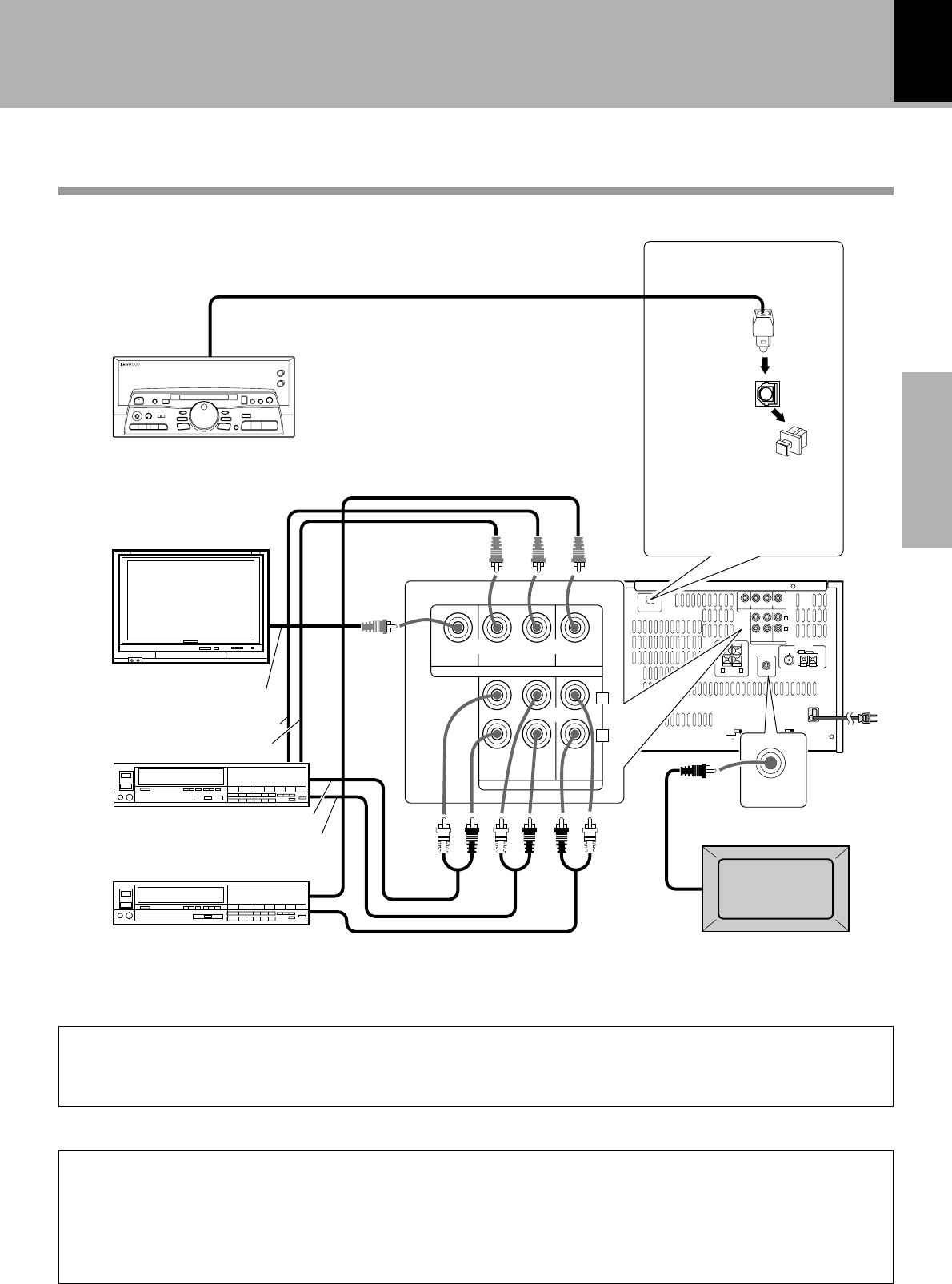
Connection of Other Accessories
(Commercially Available Parts)
MONITOR
OUT
REC OUT PLAY IN PLAY IN
VIDEO 1
VIDEO
AUDIO
REC
OUT
PLAY
IN
PLAY
IN
FM
75Ω
GND AM
VIDEO 1
AC 110–
120V
VIDEO 2
VIDEO 2
L
R
ANTENNA
DIGITAL
OUT
OPTICAL
AC 220–
240V
AC 110–
120V
AC 220–
240V
+
-
+
-
FRONT
SPEAKERS
(6 - 16Ω)
SUPER
WOOFER
PRE OUT
LR
MONITOR
OUT
REC OUT PLAY IN PLAY IN
VIDEO 1
VIDEO
AUDIO
REC
OUT
PLAY
IN
PLAY
IN
VIDEO 1 VIDEO 2
VIDEO 2
L
R
SUPER
WOOFER
PRE OUT
DIGITAL
OUT
OPTICAL
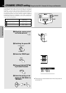
DIGITAL OUT jack
(OPTICAL)
If necessary, remove the
cap and plug the optical-
fiber cable (optional)
Cap
Optical-fiber
cable
Optical-fiber cable
MD recorder or DAT etc.
Monitor TV
Video Input
Video deck
DVD player or LD player
Audio output
Video output
Video output
Video input
Audio input
Audio output
Powered subwoofer
Only for NV-500
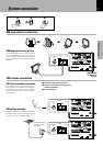
System connection
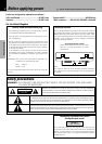
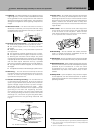
CAUTION
Be sure to adhere followings. Or proper ventilation will be blocked causing damage or fire hazard.
÷ Do not place any objects impairing heat radiation onto the top of unit.
For U.S.A. and Canada
CAUTION
Be sure to adhere followings. Or proper ventilation will be blocked causing damage or fire hazard.
÷ Do not place any objects impairing heat radiation onto the top of unit.
÷ Leave a space around the unit (from the largest outside dimension including projection) equal or greater
than, shown below.
Back panel : 10 cm
For other countries