


37
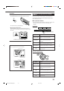
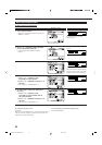
q Turning On and Off the Video Output
—VIDEO POWER
On this submenu screen, you can
turn on or off the power supply
to the video output circuit built
in this unit.
7
VIDEO POWER
Turn on or off the power supply to the video output circuit.
ON : Normally select this.
Power is supplied to the built-in video output circuit.
OFF : Select to cut off power to the built-in video output circuit
while playing an audio source.
With this setting, interference caused by the video output
circuit will be reduced.
Note:
Even if “VIDEO POWER” is set to “OFF,” power will be supplied to
the video output circuit when on-screen display menus are used.
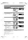
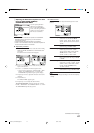
w Setting the Speakers 2 Usage—SPEAKER 2
On this submenu, you can
determine how to use the
FRONT 2 SPEAKERS
terminals.
7
SPEAKER 2
When using the FRONT 2 SPEAKERS terminals, determine the
speaker terminal usage.
SPEAKER 2 : Select to connect the second front speakers.
BI-AMP OUT : Select to connect the front speakers using bi-
amplifier connection*.
The BI-AMP indicator (as well as the front
speaker 1 indicator) will light up when the
front speakers 1 are activated.
Notes:
*
If your speaker has two pairs of input terminal (one for the high
frequency range and the other for the low frequency range),
you can connect the speakers by using both the FRONT 1
SPEAKERS and FRONT 2 SPEAKERS terminals on the rear of
this unit.
• When “BI-AMP OUT” is selected, the surround back speakers
are automatically deactivated. In this case, the SURR CH OUT
submenu cannot be adjusted (see page 36).
• When “BI-AMP OUT” is selected, “SURR BACK SP” is set to
“NONE” on the SPEAKER SETTING submenu (see page 32).
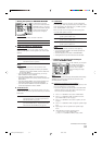
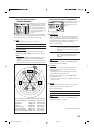
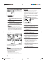
7
DIGITAL OUT
Select the output digital signal format through the DIGITAL
OUT (optical) terminal on the rear.
• Each time you press the button, the output signal format
changes as follows:
THROUGH : Select when connecting a digital signal
processor or decoder. The incoming digital
signals are transmitted through the digital output
terminal without any processing.
PCM : Select when connecting an MD recorder or other
digital recording device. The incoming digital
signals are down-mixed and converted into PCM
format.
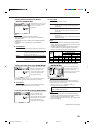
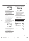
p Setting the Video Input Terminals
—VIDEO INPUT
After connecting the video
components to the video input
terminals, you have to register
which type of the terminal you
have connected to—whether the
component input or S-Video/
composite input.
Without setting this correctly,
you may not view the pictures on
the TV.
7
VIDEO INPUT
Select an appropriate input terminal used for each component—
“DVD,” “DBS,” and “VCR1.”
• Each time you press # (RIGHT) or @ (LEFT), the selected
video input terminal changes as follows:
COMPO1 “ COMPO2 “ COMPO3 “ S/C
“ (back to the beginning)
Notes:
• If you have selected the same component input terminal for
different video components, only the last performed terminal
setting will be valid. (The other terminal settings will be
automatically set to “S/C.”)
• If any of “COMPO 1/2/3” is selected for the video component
which is only connected using S-video or composite video jacks
(S/C), you cannot view or record its playback picture.
EN29-38_RX-DP20VSL[B]f.pm5 03.5.21, 18:5437