


32
AV COMPU LINK remote control system
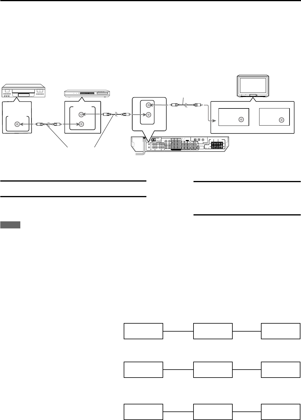
The AV COMPU LINK remote control system allows you to operate JVC’s video components (TV, DVD player and VCR) through this
receiver.
This receiver is equipped with the AV COMPU LINK-III, which has added a function to operate JVC’s video components through the video
components terminals. To use this remote control system, you need to connect the video components you want to operate, following the
diagrams below and the procedures on page 33.
• Refer also to the manuals supplied with your video components.
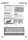
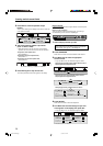
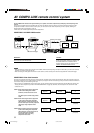
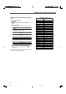
CONNECTIONS 1: AV COMPU LINK Connection
CAUTION:
When connecting the TV with the AV COMPU LINK
remote control system, connect the receiver to the
AV COMPU LINK EX or AV COMPU LINK III
terminal. DO NOT connect the receiver to the AV
COMPU LINK RECEIVER/AMP terminal.
AV
COMPU LINK
AV
COMPU LINK
AV
COMPU LINK EX
AV
COMPU LINK-
ΙΙΙ
TV
or
DVD Player
VCR
COAXIAL
AM LOOP
ANTENNA
FM 75
AM EXT
VIDEO
AUDIO
COMPONENT VIDEO
SUBWOOFER
OUT
DIGITAL IN
DIGITAL 3
(TV)
DIGITAL 2 (DBS)
DIGITAL 1
(DVD)
DVD
IN
DVD
IN
DVD IN
FRONT
SURR (REAR)
TVVCRDBS
AV
COMULINK-III
ININ
IN
(PLAY)
OUT
(REC)
RIGHT LEFT
SUB-
WOOFER
CENTER
RL
L
R
DBS IN MONITOR
OUT
DBS
IN
VCR
MONITOR OUT
VIDEO
OUT
(REC)
IN
(PLAY)
CENTER
SPEAKER
SURROUND
SPEAKERS
RIGHTLEFT RIGHTLEFT
FRONT
SPEAKERS
CAUTION:
SPEAKER
IMPEDANCE
8
~
16
Y
P
B
PR
AV
COMULINK-III
S-VIDEO
NOTES
• When connecting the receiver and a TV with the AV COMPU LINK EX terminal by using a component video cable, you cannot use Automatic
selection of TV’s input mode (see page 33).
• When connecting the DVD player or VCR and TV to this receiver, connect it directly to the receiver using cable with monaural mini-plugs.
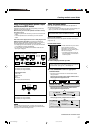
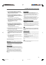
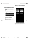
CONNECTIONS 2: Video Cable Connection
This receiver is equipped with three types of the video terminals—composite video, S-video, and component video, and the signals coming into
this receiver through one type of video terminals can output only through the terminal of the same type. So you need to connect the VCR and TV
to this receiver using one of the following three ways.
• When using the AV COMPULINK remote control system, set the component video input for the DVD player and the DBS tuner correctly (see
“Setting the video component input mode—DVD VIDEO/DBS VIDEO” on page 20); otherwise, the correct input for this receiver will not be
selected on the TV.
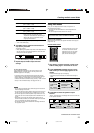
CASE 1: When connecting the source equipment
to the receiver through the S-video
terminals, connect this receiver to the
To Video Input 1
TV
RX-ES1SL
S-video cord
S-video cord
Source
Equipment
TV’s Video Input 1 terminal using S-video
cords.
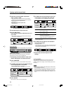
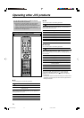
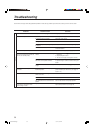
CASE 2: When connecting the source equipment
to the receiver through the composite
video terminals, connect this receiver to
the TV’s Video Input 2 terminal (composite
To Video Input 2
(Composite)
TV
RX-ES1SL
Composite
video cord
Source
Equipment
Composite
video cord
video input) using composite video
cords.
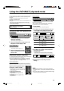
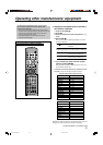
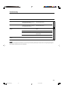
CASE 3: When connecting the source equipment
to the receiver through the component
video terminals, connect this receiver to
the TV’s Video Input 2 terminals
(component video input) using
component video cords.
To Video Input 2
(Component)
TV
RX-ES1SL
Component
video cord
Source
Equipment
Component
video cord
IMPORTANT:
The AV COMPU LINK remote control system cannot control the DBS
tuner connected to the DBS terminals.
Monaural mini-plugs
Monaural mini-plugs
32-37.RX-ES1SL[J]1 03.3.27, 5:23 PM32