


10
Typical System Configuration
—Continued
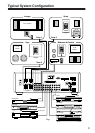
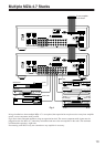
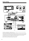
Fig 1 depicts a typical configuration, where the
MZA-4.7 is providing audio into four listening zones.
Each zone consists of a room with a pair of speakers, and
a suitable controller. Additionally a zone may require
TV’s or screens. In Fig 1 three such screens are shown in
the Lounge, Gym, and Bedroom. Each zone may be lis-
tening/watching any of the connected sources: Satellite
Receiver, DVD, Video, Digital Music Server, CD
Changer, or Tuner.
■
Controllers
Each zone has specific control requirements.
• Zone 1 - The Lounge
The ideal control in the lounge environment is from
the sofa or lounge suite.
• Zone 2 - The Study
This is a listening environment where remote con-
trols are not welcome on the busy desk. The best
solution is a wall-mounted keypad. An Integra key-
pad displays amplifier power and source selection
status. The keypad learns the source equipment IR
commands, and relays these to the equipment via the
MZA-4.7.
• Zone 3 - The Gym
An Integra keypad are used to provide additional
access to the CD changer, and SAT receiver. In addi-
tion the Keypads IR receiver is enabled so that
changes can be made using a remote while working
out.
• Zone 4 - The Bedroom
An Integra keypad is situated by the bedrooms
adjoining ensuite and provides control in that envi-
ronment. The bedroom control is via the keypad’s IR
receiver and a learning remote control.
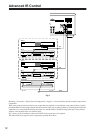
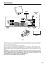
Source control IR emitters are plugged into the IR out
ports.
There are two IR ports which combine both the control-
ler inputs (IR1 + IR2). These outputs control sources
required in all zones i.e. DVD, VCR, CD and DMS. Each
controller interface has an associated IR Out port that
routes IR only to that output. In Fig 1 the SAT emitter is
plugged into IR out port IR1, which means the zone 1, 3
and 4 controllers may control the SAT source. The Tuner
emitter is plugged into IR Out port IR2, so only the zone
2 controller may control the Tuner.
■
Source Components
The MZA-4.7 has RCA audio inputs for connecting
seven stereo source components and one mono source.
The Fig 1 configuration has only six of the possible eight
sources populated.
Each zone may select from any of the connected sources.
Someone in the lounge may be listening and viewing the
DVD source, while another in the study may be listening
to music from the Digital Music server.
All four zones may even select the same source, in such
circumstances there is a possibility that all four zones
may be trying to control that source – this is not always
desirable – so a system should be well planned and
where appropriate additional source equipment
installed.
■
Speakers
Speakers in each zone are connected to the MZA-4.7 by
“Home-Run” speaker cables.
Each zone has a maximum loading of 6 ohms.
Fig 1 depicts a powered subwoofer in the study. The
subwoofer is driven by the zone 2 preamplifier, and is set
to track the zone 2 amplifier volume. The subwoofer vol-
ume or offset can be adjusted for correct tonal balance.
Fig 1 additionally depicts a pair of speakers in the bed-
room. These are the associated bedroom ensuite speak-
ers and are driven by a low powered slave amplifier. The
zone 4 preamplifier has been set to “Independent” mode
and connects to the low powered slave amplifier.
Independent mode is where the preamplifier volume
may be different from the amplifier volume (within a
range of 68), it also has independent Standby and Mut-
ing.
■
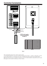
Video Outputs
The composite video outputs are suitable for driving
ONE composite video display device. To avoid signal
degradation, home runs of appropriate video cable
should be less than 100 meters.