


Rev 3, March/2007 ©Honeywell International Inc. Do not print without express permission of Honeywell. 2-2
KNI 582
2. The above step should be repeated for at least one additional heading 90°
from the first.
B. ADF Accuracy
1. Depending on the application, the KNI 582 RMI can be tested for either DC
SIN/COS ADF or X, Y, Z, ADF by tuning in a station on the appropriate ADF.
2. In the DC SIN/COS Mode the needles should position the direction of the
station +5°. Repeat for at least one more station.
3. Repeat Step 2 for X, Y, Z, ADF +5°.
C. VOR Accuracy
1. Depending on the application, the KNI 582 RMI can be tested for either OBI
DIGITAL VOR, COMPOSITE VOR, or OBI SIN/COS VOR by tuning in a
station on the appropriate VOR.
2. In the OBI DIGITAL VOR Mode, the single needle should point to the station
+5°. Repeat for at least one more station.
3. Repeat Step 2 for COMPOSITE VOR +5°.
4. Repeat Step 2 for OBI SIN/COS VOR +5°.
D. VOR/LOC Composite Correction Adjustment
If it is necessary to make a VOR/LOC composite needle centering adjustment
due to NAV receiver composite error, the KNI 582 RMI pointer can be adjusted
externally using the following steps:
1. With a ramp-test NAV generator, generate an output so the NAV receiver can
be tuned into a given bearing.
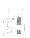
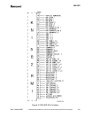
2. With the NAV receiver tuned to the generator frequency, insert a tuning tool
into VOR/LOC composite adjustment hole (refer to Figure 2-1) and adjust
R232 until the selected needle reads the same bearing the ramp generator.
3. Repeat Step 2 for verification of the adjustment for another bearing on the
ramp with generator.