


Rev 3, March/2007 ©Honeywell International Inc. Do not print without express permission of Honeywell. 1-3
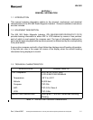
KNI 582
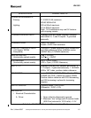
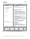
SPECIFICATION CHARACTERISTIC
B. Receiver 1. Input resistance = 1K ± 5% returned to +V
2. +V = 9.0V ± 15%
C. Interconnecting Lines 1. Maximum Shunt Capacity = 2000 pF
II Waveform Timing
A. Data 1. Data Rate - Approx. 1KHz
2. Negative Logic (“Low True”)
B. Clock 1. The negative going edge of the clock
waveform will be greater than 10us and less
than 250us from any data transistors point.
2. The minimum time that the clock spends in
either the high or low state will be greater
than 10us.
C. Sync 1. The sync pulse is a negative going pulse
following the data word.
2. The negative going edge of the sync pulse
will be a minimum of 70us and a maximum of
350us after the negative going edge of the
last clock pulse.
3. The sync pulse will be a minimum of 10us
wide and a maximum of 260us wide.
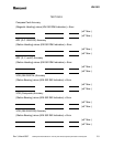
III Data Word Format 1. BCD, 0.1’s, 1’s, 10’s, 100’s
2. LSD to MSD
3. LSB to MSB
4. Maximum Word Rate = 12Hz
5. When “8” Bit of 100’s is High (False) = Flag.
6. When “4” Bit of 100’s is High (False) = ILS
Mode.
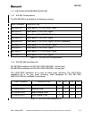
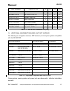
100° 10° 1° .1°
(8)
Flag
(4)
ILS 2 & 1 MSB LSB MSB LSB MSB LSB ABC
<---- Time
Table 1-1 - KNI 582 RMI Technical Characteristics (Cont)