


Rev 3, March/2007 ©Honeywell International Inc. Do not print without express permission of Honeywell. 1-2
KNI 582
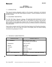
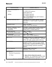
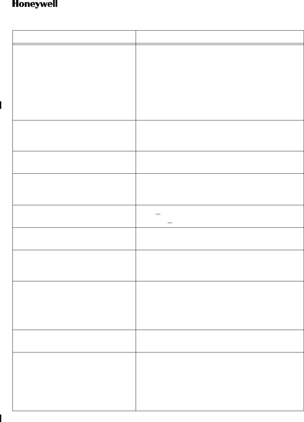
SPECIFICATION CHARACTERISTIC
POWER REQUIREMENTS
Primary: 11.33VDC 0.4A maximum
26VAC 400Hz 6VA
Lighting: 28V at 80mA maximum
5V at 460mA maximum
Note: 14V Installations may use 5V Versions
with dropping resistor.
COMPASS HEADING INPUT Operates from any slaved magnetic compass
with ARINC X, Y, and Z outputs. Z grounded
externally.
COMPASS VALID Valid = +27.5VDC
Invalid = 0VDC 2mA maximum
VOR/LOC COMPOSITE INPUT
(-04 Version TACAN
Compatible)
0.5VRMS 0° phase composite 30Hz variable AM
and 30Hz reference FM on a 9960Hz carrier
(ARINC Std.) (0.7VRMS maximum)
NAV SUPERFLAG
(Horizontally parked needle)
Flag < +3.5VDC
No Flag > +10VDC
ILS ENERGIZE
(Horizontally parked needle)
ILS < +1VDC (GND)
VOR = Open (+33VDC Maximum)
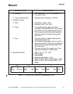
ADF X, Y, Z Operates from any ADF receiver with ARINC X,
Y, Z outputs. Z grounded externally. 11.8VRMS
400Hz 180° index, positive rotation reference.
OBI SIN/COS 4 wire SIN/COS 10VRMS 400Hz. 0° when SIN =
0VRMS and COS = maximum positive VRMS.
Positive rotation reference with COS decreasing
and SIN increasing in-phase for increasing
degrees.
ADF DC SIN/COS Common Mode: 0 to ± 5VDC
Differential: 3VDC ± 10%
OBI DIGITAL
I Electrical Characteristics
A. Driver 1. Open collector referenced to ground
2. Maximum “low” voltage (with 2 receiver loads
(500 Ohm) returned to 10.35 volts) = 1.0V.
Table 1-1 - KNI 582 RMI Technical Characteristics (Cont)