


contents
HP 86736/D
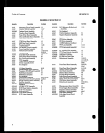
LIST OF ILLUSTRATIONS (cont’d)~
Figure
8-60.
8-61.
8-62.
8-63.
8-64.
8-65.
8.66.
8-67.
8.68.
8-69.
8-201.
8.202,
S-203.
8.204.
S-205.
8.206.
8.207.
8.208.
8.209.
8.210.
8-211.
8-212.
8-213.
8.214.
8.215.
Page
Pulse Driver Board, Input and
Series Pulses . .8-79
Bias Tee . . . . . .8-80
Pulse Driver Board, Input Pulse and
SamplePulae * *... . . ..*...**....*.8-81
HP 8678C/D Pulse Modulation,
Block Diagram , *. . . . ,841
Front Panel Keyboard and Indicator
Block Diagram . . .8-82
M/N Phase Detector, LFS Loop DAC
and 20/30 Divider Block Diagram.. .8-84
A5 Downconverter Microprcceaaor/
Controller Block Diagram ,845
Sample Error Printout . . . . .8-104
HP 9825A and HP 85F Sample
PrOgKam L&ng.. . . 8-105
HP 8673WD Controller Assembly,
Block Diagram . . . .8-127
A3AlAl Reference Phase Detector
Assembly Component and Test
Point Location . . , . , , . , , .8-201
Reference Phase Detector Assembly
Schematic Diagram , , , . , . , , , , . , , . , .8-201
A3A1A2 100 MHz VCXO Assembly
Component and
Test
Point
Location
tttttttttti..... < . . 8-203
100 MHz VCXO Assembly
Schematic Diagram , , , . , , , , . . t . .8-203
A3AIA3 M/N Phase Detector Assembly
Component and Test Point
Location , , , . , t , t S-205
M/N Phase Detector Assembly
Schematic Diagram . . . .8-205
A3AlA4A2 M/N VCO Board Assembly
Component and Teat Point
Location .8-207
M/N VCO Assembly
Schematic Diagram
t t t . .8-207
A3AlA5 M/N Output Assembly
Component and Teat Point
Location t.t,ttt.ttt <I< t.............. 8-209
M/N Output Assembly
Schematic Diagram . . , . , . , . .8-209
A2A5 20/30 Divider Assembly
Component and Test Point
Location . . . .8-211
20/80 Divider Assembly
Schematic Diapram . . . . . . .8-211
A2A4 20/30
Phase Detector Assembly
Component and Teat Point
Location . . . . . . . .8-213
20/30 Phase Detectcr Assembly
Schematic Diagram , . , , . , . . , . , , . , S-213
A2A3 VCO 160-240 MHz Assembly
Component and Test Point
Location * * * . t t . , t < t . t t , t t t t <. . .8-215
Figure
Page
8-216.
8.217.
8-218.
8-219.
8.220.
8-221.
8.222.
8-223.
8-224.
8-225.
8.226.
8-227.
8-228.
8.229.
E-230.
S-231.
5232.
S-233.
8-234.
S-235.
8-236.
8-237.
VCO 160.240 MHz Assembly
Schematic Diagram &215
A3A5 DAC Assembly
Component and Teat point
Location . .8-217
Digital to Analog Converter Assembly
Schematic Diagram . . . .8217
ASA YTO Driver Assembly
Component and Test Point
Location . 8-219
YTO Driver Assembly
Schematic Diagram . . .8-219
A3A9A5 Sampler Assembly
Component and Test Point
Location . . . .8-221
P/O YTO Loop Assembly
Schematic Diagram . . . .8-221
A3A9A4 YTO Phase Detector Assembly
Component and Test Point
Location . . .1. . . . .8-223
P/O YTO Loop Assembly
Schematic Diagram . . . . . .8-223
A3A7 YTO/l?M Coil Driver Assembly
Component and Teat Point
b&ion . . , , . t . . . t . . J-225
YTO/FM Coil Driver Assembly
Schematic Diagram , , , , , . , t *, . , . , . ,8-225
AlA2Al Detector/!&C Assembly
Component and Teat Point
tocation . . .&227
Detector/ALC Assembly
Schematic Diagram . .8-227
AlA Pulse Driver Processing Assembly
Component and Test Point
Location . . . . . . . . . .8-229
P&s Driver Processing
Assembly Schematic . . . .8-229
AlA YIG Driver Board Assembly
Component and Teat Point
Location . .8-281
AlAOAl YIG Aaeembly
Component and Test Point
Location . . . . . . .8-231
YIG Driver Assembly
Schematic Diagram :. . . . . .8-231
AlA Detector Board Assembly
Component and Test Point
Location . . . . . . . .8-288
AlA14A1 Bias Board Assembly
Component and Test Point
Location . . . . . . S-233
RF Filter Circuits Component
Location (86730 . . . . .8-284
P/O RF Filter, RF Amphfier, and
D&c& Amplifier Circuits, 8673C
(to be used with Figure 8-239) t , < . . t .8-235