


Contents
HP 861X/D
CONTENTS
(oont’d)
Page
Non-Repairable Assemblies.. .,. . .8-E
Factory Selected Componenta (*) . . . t . . . .8-l-/
Cleaning . ttt.11ttt11tt . . . ..*.*t t............. 8-17
Cleaning Intervals . .8-17
Cleaning Solution . . . . , , t.. , , t 8.11
Top Cover Removal and Replacement .8-1’7
Page
6.Month Cleaning .8-17
la-Month Cleaning , . , . , , , , . , . , . . , , , , . , t , , . , . ,8-18
Schematic Symbology . . . . . . . . . . . . . . . . . . . . . . . . . . .820
Basic Logic Symbology . . . . . .8-20
Complex Device Symbology t t . t . t t . . t . t . t . t . t .8-20
LIST OF ILLUSTRATIONS
5-l.
5-2.
s-a.
5.4.
55.
5.6.
5-7.
5-8.
5-9.
510,
5-n
5.12.
6-13.
5-14.
6-16.
5-16.
5-17.
5.18.
Title Scxcen
................................ .5-2
Main Menu ................................ .5-2
Adjustment Software
....................... t5-3
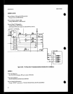
Power Supply Adjustment Test Setup
...... .&IO
10 MHz Reference Oscillator Adjustment
Test Setup .............................. .5-12
Reference Loop (VCXO) Adjustment
Test Setup
.............................. .5-13
M/N Loop Adjustment Test Setup ......... .8-16
20/30 MHz (LFS) Loop Divider Bias
Adjustment Teat Setup .................. ,518
LFS Loop Notch Filter Adjustment
Test
Setup .............................. .5-22
YTO Loop Sampler Adjustment
T&Setup..
........................... ..5-2 7
Sampler Frequency Response.. ............
,528
YTO Loop Offset and FM Overmodulation
Adjustment Test Setup .................. .5-30
YTO Loop Offset Adjustment
Wavefoma
............................. ,531
YTO Loop Phase Detector Adjustment
Ted setup .............................. .5-88
Spectrum Analyzer Display of Phaee
LockedLoopEain
....................... ,684
FM Driver Adjustment
Test Setup
......... .5.36
FM Accuracy and Overmodulation
Adjustment Test Setup .................. .6-37
Format
for
Entering SRD Bias
Voltages for 8673D ...................... .5-39
8.19. Gate Voltage Adjustment for 867330
......... K-40
5.20. SRD Bias Adjustment Test Setup ..........
,540
5.21. Optimum YTM Response .................. : .5-42
5.22. YTM Tune Adjustment Test Setup . , . , . , , . ,5-43
6.28. Power Clamp Adjustment
Test
Setup ...... .6-44
5-24, Utility Menu
.............................. .5-45
6.25. Maximum Power Tests Menu .............. .5-46
5-26. Maximum Power for 8673D ................ .5-46
5-27. PT’P Adjustment Test Setup
............... ,547
5.28. YTF DAC Adjustment
..................... .5-48
5-29. YTF Passband Response
.................. ,549
5.30. Maximum Power Menu .................... .5-50
5-81. Maximum Power, Normal
Mode
for 8673D ............................... .5-51
5-32. 4.2 GHz Oscillator Adjustment
Test Setup
.............................. .5-52
6.1. HP 8673C/D
Parts
Identification . . .6-107
6-2. Interconnecting Parts Identification . . . .&IO8
6-8. Upper Unit Overall Parts Identification. . . .6-109
6-4. Upper Unit Cabinet Pati Identification . .6-110
6-6. Upper Unit Front Panel Parts
Identification . . . . . . . . .6-111
6.6. Al Microwave Circuits
Parts
Identification . . . . . . . . . . t I . . .6-112
iv
I
Figure Page
5.33. Low Band Clamp Adjustment
Test Setup .............................. .&53
5.34. Maximum Power Menu ....................
,554
5-35.~wBandClampResponae ................
.554
586. Low Band Maximum Power ...............
.5-55
5.37. 8673D Maximum Power with K-Band
(16-26 GHz) Amplifier ................... .,5-55
5.38. Flatness and ALC Adjustment Menu
...... .5-56
5-39. Typical Flatness Plot Before
Adjustment .............................
,557
6.40. Flatness Adjustment Display .............. ,558
5.41. Flatness and ALC Adjustment
Test Setup .............................. .5-59
5.42. AM Bandwidth Adjustment Test Setup
.... .560
5.43. AM Accuracy and Meter Adjustment
Teat Setup .............................. .5-63
5.44. Bias-2 DAC Adjustment Test Setup ,
....... .5-66
5-45. Series Pulse Width Adjustment
Teat
Setup ...............................
.5-66
M6. Series Pulse Width Waveform ..............
.5-67
547. Pulse Shunt Adapter .......................
E-68
5.48. AIL Sample Pulse Adjustment Setup ...... .5.69
5.49. ALC Sample Pulse Waveform .............. E-70
5.50. Pulse Program Menu ......................
.5-71
5.51. Pulse Amplitude Control Band
We&Menu ............................
..S? 2
E-52. PAC Adjustment Menu .................... .5-73
558. Pulse Scan Menu ..........................
,674
5.54. EraphRoutieehintout ................. ...5-15
6.55. Print Routine Printout ....................
.5-75
5.56. Pulse Amplitude Control Adjusltment
Test Setup ........... ., ................... .5-76
5.57. Sweep Out and 13lanking/Marker
Adjustment Test Setup .................. .577
5.58. Sweep Out Waveform .....................
.578
5.59. Marker Waveform ......................... ,578