


HP 8673C/D
contents
CONTENTS
Sections I through III
and Section IV Part I
GENERAL INFORMATION
INSTALLATION
OPERATION
OPERATION VERlFlCATlON
These sections are bound separately with a separ-
ate table of contents.
Section IV, Part 2
PERFORMANCE TESTS
Page
Introduction ..... / . , , ...................... .4-l
Section
V
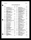
ADJUSTMENTS
Introduction .....................................
.5-l
Safety Consideration&
........................... ,5-l
Equipment Required
............................. .5-l
Identical Circuit Board Assemblies ...............
.5-l
Automated Adjustment Procedures ............... .5-l
Factory Selected Components ....................
,5-Z
Related Adjustments
............................ .5-2
Power Supply Adjustments
..................... .5-10
10 MHz Reference OadXlator Adjustment
........ .5-12
Reference Loop (VCXO) Adjustment
............ .5-13
M/N Loop Adjustments
........................ .5-16
20/30 MHz (LFS) Loop Divider Bias
Adjustment ..................................
.5-18
160-240 MHz (20130 MHz or LFS Loop)
vco Pretune ................................. .5-20
LFS Loop Notch Filter Adjustment ..............
,522
YTO Pretune Digital-to-Analog Converter
Adjustment ..................................
.5-24
YTO Driver Adjustment
........................ .5-26
YTO Loop Sampler Adjustments ................
.5-27
YTO Loop Offset and FM Overmodulation
Adjustments .................................
,530
YTO Loop Phase Detector Adjustments
......... .5-33
FM Driver Adjustments ........................
.5-36
FM Accuracy and Overmodulation
Adjustments .................................
,537
SRD Bias Adjustment ..........................
.6-39
YTM Tune Adjustment .........................
.5-42
Clamp Adjustment .............................
.5-44
YIG Tuned Filter Adjustment
................... .5-47
4.2 GHz Oscillator Adjustment.
................. .5-52
cw LO Clamp Adjustment
..................... .5-53
Flatness and ALC Adjustments .................
,636
AM Bandwidth Adjustment .....................
,540
AM Accuracy and Meter Adjustment.
............ 5-63
Pulse Modulation Adjustment
................... .8-65
Pulse Amplitude Control Adjustment ............
.5-71
Sweep Out and Blanking/Marker
Adjustments .................................
.5-71
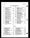
Section VI
REPLACEABLEPARTS
Introduction ....................................
.,6-l
Restored Assemblies
............................. .6-l
Page
Abbreviations ...................................
.6~1
Replaceable Parts List
........................... .6.1
FactorySelectedPartEi(*) ...... tt ...............
6-l
Parts List Backdating (f) ......................
.6-l
Part6 List Updating ...........................
.6-l
Ordering Information ...........................
.6-l
Parts Identification ..............................
.6-2
Recommended Spares List
..... , , ................
.6-2
Section VII
MANUAL CHANGES
Introduction
.....................................
.7-l
Instrument Improvement Modifications
..........
.7-l
Improved Key Code Debouncing (Instrumenta
with serial number prefix 2332A). ............
.7-l
Firmware Update Kit
.......................... .7-l
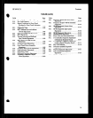
Section VIII
SERVICE
Introduction .....................................
.81
Failure Modes and Service Strategy
..........
. ... .8-I
General........................................8 -1
Turn-on Errors ................................
.8-l
OperatorErrors..
............................ ..8 .l
Instrument Perforxsance out of
Specification
................................
.8-l
Catastrophic Failures .........................
.8-l
Service Sheets ...................................
.8-l
Manual Backdating (f)
..........................
.8-2
Manual Updating
(Manual Changes Supplement)
........ . ....... .8-2
Safety Considerations
............................
S-2
Before Applying Power ........................
.8-2
Warnings and Cautions .......................
.8-2
After Swvice Safety Checks.
................... -8-3
Recommended Test Equipment ..................
.8-3
Service Tools, Aids and Information
............. .8-3
Service Accessotiea ............................
,823
Service Functions ...... + . . ....................
.8-3
Signature Analysis ............................
.8-3
Pozidriv Screwdrivera .........................
.8.3
Tuning Tools
..................................
.8-3
Heat Staking Tools ............................
.8-3
Hardware ....................................
.8-I2
Assembly Locations ..........................
.a-12
Parts and Cable Locations .....................
8-12
Test Points and Adjustment Looatiooes ........
.8-13
Service Aids on Printed Circuit Boards ........
.8-13
Other Service Documents ..................... .8-13
Repair and F&placement
........................
.8-13
After Repair Adjustment Procedure ...........
.8-13
Disassembly and Reassembly Procedures
..... *S-13
Top and Bottom Cover Removal ..............
.8-13
Front Panel Key Cap Replacement ............
.8-13
Front Panel Switch Replacement
.............. .8-13
Etched Circuits (Printed Circuit Boards).
...... ,814
Electrostatic Discharge @SD) Precautions
.... .8-15
Module Exchange Program ...................
.8.15