


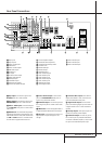
6 FRONT PANEL CONTROLS
Front Panel Controls
7
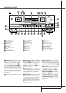
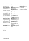
Surround Mode Selector: Press this but-
ton to change the surround mode by scrolling
through the list of available modes. Note that
Dolby Digital and DTS modes can be selected
only when a digital input is used (See page 26
for more information about surround modes.)
8
Tuning Selector: Press the left side of the
button to tune lower frequency stations and the
right side of the button to tune higher frequency
stations. When a station with a strong signal is
reached, the TUNED indicator
W
will illuminate
in the Main Information Display
Ú
(see
page 31 for more information on tuning sta-
tions).
9
Tuner Band Selector: Pressing this button
will automatically switch the AVR to the Tuner
mode. Pressing it again will switch between the
AM and FM frequency bands, holding it pressed
for some seconds will switch between stereo
and mono receiving and between automatic and
manual tuning mode (See page 31 for more
information on the tuner).
)
Preset Stations Selector: Press this but-
ton to scroll up or down through the list of sta-
tions that have been entered into the preset
memory. (See page 31 for more information on
tuner programming.)
!
Input Source Selector: Press this button
to change the input by scrolling through the list
of input sources.
@ RDS Select Button: Press this button to dis-
play the various messages that are part of the
RDS data system of the AVR 3000’s tuner. (See
page 32 for more information on RDS).
#
Digital Optical 3 Input: Connect the opti-
cal digital audio output of an audio or video prod-
uct to this jack.When the Input is not in use, be
certain to keep the plastic cap installed to avoid
dust contamination that might degrade future
performance.
$
Digital Coax 3 Input: This jack is normally
used for connection to the output of portable
digital audio devices, video game consoles or
other products that have a coax digital jack.
%
Video 4 Input Jacks: These audio/video
jacks may be used for temporary connection to
video games or portable audio/video products
such as camcorders and portable audio players.
^
Bass Control: Turn this control to modify the
low frequency output of the left/right channels by
as much as ±10dB. Set this control to a suitable
position for your taste or room acoustics.
&
Balance Control: Turn this control to
change the relative volume for the front
left/right channels.
NOTE: For proper operation of the surround
modes this control should be at the midpoint or
“12 o’clock” position.
*
Treble Control: Turn this control to modify
the high frequency output of the left/right chan-
nels by as much as ±10dB. Set this control to a
suitable position for your taste or room acoustics.
(
Volume Control: Turn this knob clockwise
to increase the volume, counterclockwise to
decrease the volume. If the AVR is muted,
adjusting volume control will automatically
release the unit from the silenced condition.
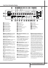
Ó
Set Button: When making choices during
the setup and configuration process, press this
button to enter the desired setting as shown in
the Main Information Display
Ú
into the
AVR 3000’s memory. The set button may also be
used to change the display brightness.
(See page 34.)
Ô
Input indicators: A green LED will light in
front of the input that is currently being used as
the source for the AVR 3000.
Delay: Press this button to begin the
sequence of steps required to enter delay time
settings. (See page 21 for more information on
delay times.)
Ò
Digital Input Selector: When playing a
source that has a digital output, press this
button to select between the Optical
# Q
and Coaxial
$ R
Digital inputs. (See pages
27-29 for more information on digital audio.)
Ú
Main Information Display: This display
delivers messages and status indications to help
you operate the receiver. (See pages 7–8 for a
complete explanation of the Information
Display.)
Û
Channel Select Button: Press this button
to begin the process of trimming the channel
output levels using an external audio source.
(For more information on output level trim
adjustment, see page 30.)
Ù
Speaker Select Button: Press this button
to begin the process of selecting the speaker
positions that are used in your listening room.
(See page 19 for more information on setup and
configuration.)
ı
Test Tone Selector: Press this button to
begin the process of adjusting the channel out-
put levels using the internal test tone as a refer-
ence. (For more information on output level
adjustment, see page 22.)
ˆ
Surround Mode Indicators: A green LED
will light in front of the surround mode that is
currently in use.
˜
Remote Sensor Window: The sensor
behind this window receives infrared signals
from the remote control.Aim the remote at this
area and do not block or cover it unless an
external remote sensor is installed.