


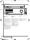
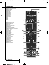
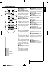
10 REAR PANEL CONNECTIONS
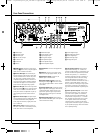
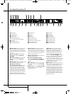
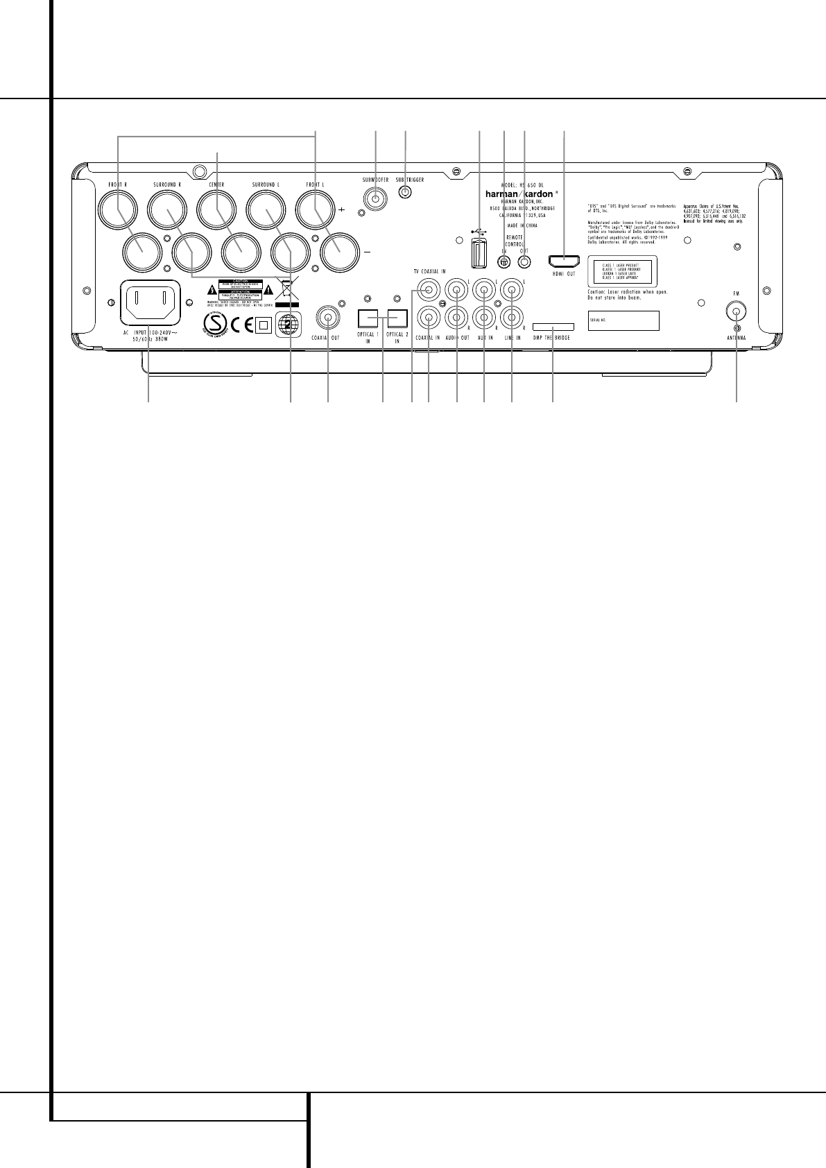
Rear Panel Connections
0
C
123F7B
4E
D
98GA6I H 5
0
HDMI Output
1
Remote IR Output
2
Remote IR Input
3
USB On-The-Go Input
4
AC Power Cord
5
FM Antenna
6
Audio In
7
Subwoofer Output
8
Coaxial Digital TV Input
9
Optical Digital Input
A
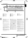
Analog Audio Outputs
B
Front Speaker Outputs
C
Center Speaker Outputs
D
Surround Speaker Outputs
E
Coaxial Digital Output
F
Subwoofer Trigger Output
G
Coaxial Digital Input
H
DMP The Bridge Input
I
Analog Audio Inputs
0
HDMI Output: Connect this output to the
HDMI input
J
of the screen, using the supplied
HDMI - SP-DIF - Remote In/Out cable.
1
Remote IR Output: This connection per-
mits the IR sensor in the receiver to serve other
remote controlled devices. Connect this jack to
the “IR IN” jack on Harman Kardon or other
compatible equipment. Note this connection is
only necessary for optional, additional products
connected to the player. It is not necessary for
proper control of the Digital Lounge system.
2
Remote IR Input: Connect this input to the
Remote IR Output
U
of the TV, using the special
HDMI - SP-DIF - Remote In/Out cable. This will
allow you to control all components in your sys-
tem by pointing the remote control to the TV
only.
3
USB On-The-Go Input: This input may be
used to temporarily connect a USB thumb device
or portable hard disk for direct playback of
audio, image of video files, a digital photo cam-
era or a USB hub.
4
AC Power Cord: Connect this plug to an
AC outlet. If the outlet is controlled by a switch,
make certain that it is in the ON position.
5
FM Antenna: Connect to the supplied FM
antenna.
6
Audio In: Connect to a line-level analog
audio source: TV, tape player, Minidisc, PC, etc.
7
Subwoofer Output: Connect to the
SUB/LFE input on the subwoofer.
8
Coaxial Digital TV Input: Connect the
Coax Digital TV Output
H
of the screen to this
jack, using the supplied HDMI - SP-DIF - Remote
In/Out cable.
9
Optical Digital Input: Connect the optical
digital output from a DVD player, HDTV receiver,
LD player, MD player, satellite receiver or CD
player to this jack. The signal may be either a
Dolby Digital signal, DTS signal or a standard
PCM digital source.
A
Analog Audio Outputs: Connect these
jacks to the RECORD/INPUT jacks of an optional
audio recorder for recording.
B
Front Speaker Outputs: Connect these
outputs to the matching + or – terminals on
your left and right speakers. In conformance with
the new CEA color code specification, the White
terminal is the positive, or "+" terminal that
should be connected to the red (+) terminal on
Front Left speaker with the older color coding,
while the Red terminal is the positive, or "+"
terminal that should be connected to the red (+)
terminal on Front Right speaker. Connect the
black (–) terminals on the Digital Lounge system
to the black (–) terminals on the speakers. See
page 19 for more information on speaker polari-
ty.
C
Center Speaker Outputs: Connect these
outputs to the matching + and – terminals on
your center channel speaker. In conformance
with the new CEA color code specification, the
Green Terminal is the positive, or "+" terminal
that should be connected to the red (+) termi-
nal on speakers with the older color coding.
Connect the black (–) terminal on the Digital
Lounge system to the black negative (–) terminal
on your speaker. (See page 19 for more informa-
tion on speaker polarity.)
0007CSK - DigitalLounge 632_640_646 ENG v11.qxp:0007CSK - DigitalLounge 632,640,646 UK 12/06/08 11:09 Side 10 (Sort/Black plade