


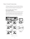
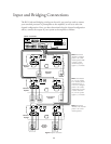
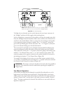
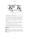

To bridge the two channels, put the switch between the two input connectors in
the “Bridged” position with the toggle switch pointing down.
In this configuration, connections to the speakers receiving the normal power feed
from the unbridged channels should be made to the connectors for Channels One
and Two in the normal fashion. That is, connect the wire running to each speaker
to the appropriate output channel as marked. The “+” or “positive” connection
goes to the top binding post with the red barrel. The “-” or “negative” connection
goes to the bottom binding post with the black barrel.
The connection for the higher power, (bridged) channel should be following the
connection diagram between the speaker connection binding posts for Channel
Three and Four. Connect the “+” or positive connection going to the binding post
marked “+” for Channel Three to the “+” or “red” terminal on the speaker. The
connection going to the negative terminal on the speaker should be connected to
the binding post marked “+” for Channel Four. (Figure 2B)
To complete the bridging of the circuits, use one of the jumpers packed with the
5.1 to make a connection between the Negative (“-”) speaker connection terminals
for Channel 3 and Channel 4 as shown in Figure 2B.
WARNING: The jumper connection should not be made when the amplifier is
turned on. This connection must be made before operating the amplifier in a
bridged mode.
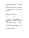
Two-Channel Operation:
In this mode two high-powered channels are provided for subwoofer use, or for
high-powered conventional stereo applications. Using high quality interconnect
cables, connect one output from your preamp or processor to the input connector
marked “Channel One”, and the other to the input connector marked “Channel
Three”. The input connectors for channels Two and Four are not used in this con-
figuration. (Figure 2C)
15
BRIDGEDBRIDGED
REMOTE
REMOTE
TURN ON
DC
IN
ON
OFF
MANUAL
TURN ON
DC
OUT
+
–
+
–
+
–
CH 1 INPUT
(BRIDGED INPUT)
BRIDGED
MODE
CH 2 INPUT
(NOT USED IN
BRIDGED MODE)
NORMAL
MODE
BRIDGED
CH 1 OUTPUT CH 2 OUTPUT
+
–
+
–
+
–
CH 3 INPUT
(BRIDGED INPUT)
BRIDGED
MODE
CH 4 INPUT
(NOT USED IN
BRIDGED MODE)
NORMAL
MODE
BRIDGED
CH 3 OUTPUT CH 4 OUTPUT
TO PROCESSOR
– + – + – +
Figure 2B Three-Channel Operation
Note: Switch on left (ch. 1 & ch. 2) is in the “Up” or “Normal” position.
Switch on the right (ch. 3 & ch. 4) is in the “Down” or “Bridged” position.
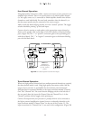
Speakers