


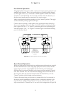
Four-Channel Operation:
Using high quality interconnect cables, connect one output of your processor to an
amplifier input channel. There is no special priority as to which specific channel
(i.e. left, right, center, etc.) is connected to which amplifier channel when all four
channels are used individually. You need only remember what the channel is, so
that the proper speaker may be connected to the correct output.
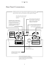
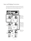
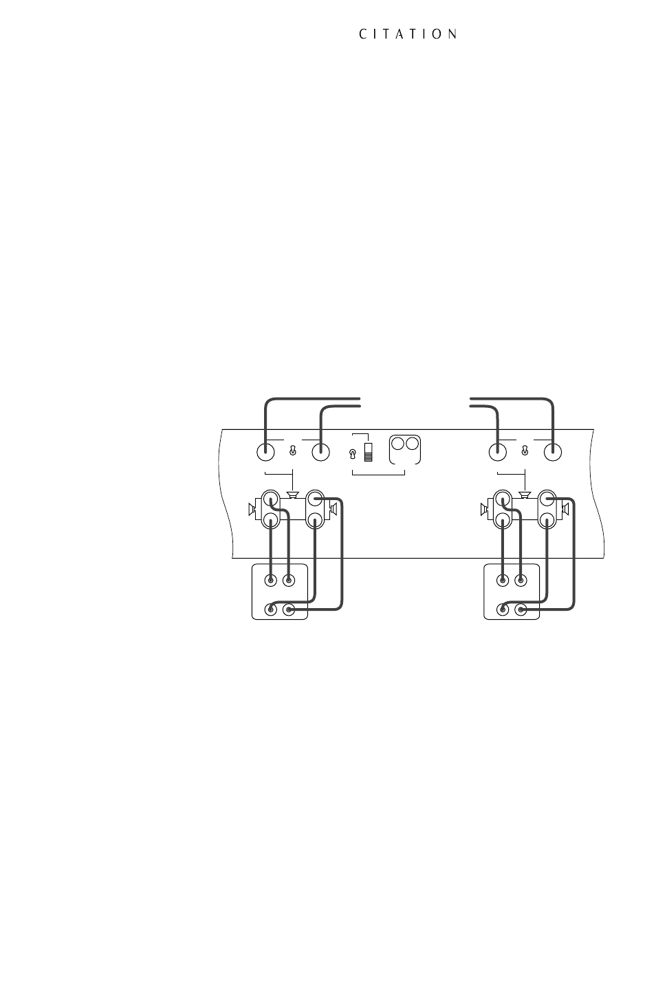
Make certain that both bridging switches are in the “normal” position. The toggle
switches should be pointing up for both inputs.
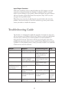
Connect the wire running to each speaker to the appropriate output channel as
shown on the speaker icons to the right or left of the speaker connection binding
posts. (Figure 2A) The “+” or “positive” connection goes to the top binding post
with the red barrel. The “-” or “negative” connection goes to the bottom binding
post with the black barrel.
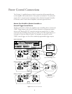
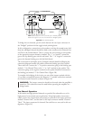
Three-Channel Operation:
When one high-powered channel and two medium-powered channels are required,
the three-channel mode is used. Using high quality interconnect cables, link the
output of your processor or preamplifier for the moderate powered channels
(left/right front or surround channels) to the input connectors marked “Channel
One” and “Channel Two”. Be certain that the bridging switch on the left side of
the rear panel, above the inputs for Channel One and Channel Two, is in the
“Normal” position with the toggle switch pointing up.
Connect the output from your processor or preamp which is to be connected to
the higher powered amplification channel (center or subwoofer channels) to the
input connector marked “Channel Three” on the rear of the Citation 5.1. The
input connection for “Channel Four” is not used in this configuration. (Figure 2B)
14
BRIDGED BRIDGED
Single Drive/Side Input
Back Input
— +
REMOTE
REMOTE
TURN ON
DC
IN
ON
OFF
MANUAL
TURN ON
DC
OUT
+
–
+
–
+
–
CH 1 INPUT
(BRIDGED INPUT)
BRIDGED
MODE
CH 2 INPUT
(NOT USED IN
BRIDGED MODE)
NORMAL
MODE
BRIDGED
CH 1 OUTPUT CH 2 OUTPUT
+
–
+
–
+
–
CH 3 INPUT
(BRIDGED INPUT)
BRIDGED
MODE
CH 4 INPUT
(NOT USED IN
BRIDGED MODE)
NORMAL
MODE
BRIDGED
CH 3 OUTPUT CH 4 OUTPUT
Single Drive/Side Input
Back Input
— +
TO PROCESSOR
Figure 2A Four-Channel Operation with Dual Drive Dipoles
Note: Both
Bridge/Normal
switches should point
Up to the “Normal”
position.