


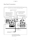
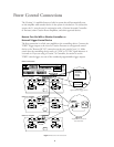
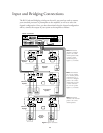
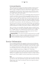

Input and Bridging Connections
The RCA jacks and bridging switches on the unit’s rear panel are used to connect
your surround processor or preamplifier to the amplifier, as well as to select the
channel configuration. Once you have determined what the channel configuration
will be, connect the output of your system to the amplifier as follows:
13
BRIDGED
BRIDGED
BRIDGEDBRIDGED
BRIDGED
BRIDGED
–+
–+
–+ –+ –+
Single Drive/Side Input
Back Input
Single Drive
Dipole
4Ω
Dual Drive
8Ω /ch.
Single Drive
Point Source
4Ω
CAUTION: Please refer to owner's manual
before making any electrical connection
to this speaker.
Single Drive/Side Input
Back Input
Single Drive
Dipole
4Ω
Dual Drive
8Ω /ch.
Single Drive
Point Source
4Ω
CAUTION: Please refer to owner's manual
before making any electrical connection
to this speaker.
REMOTE
REMOTE
TURN ON
DC
IN
ON
OFF
MANUAL
TURN ON
DC
OUT
+
–
+
–
+
–
CH 1 INPUT
(BRIDGED INPUT)
BRIDGED
MODE
CH 2 INPUT
(NOT USED IN
BRIDGED MODE)
NORMAL
MODE
BRIDGED
CH 1 OUTPUT CH 2 OUTPUT
+
–
+
–
+
–
CH 3 INPUT
(BRIDGED INPUT)
BRIDGED
MODE
CH 4 INPUT
(NOT USED IN
BRIDGED MODE)
NORMAL
MODE
BRIDGED
CH 3 OUTPUT CH 4 OUTPUT
REMOTE
REMOTE
TURN ON
DC
IN
ON
OFF
MANUAL
TURN ON
DC
OUT
+
–
+
–
+
–
CH 1 INPUT
(BRIDGED INPUT)
BRIDGED
MODE
CH 2 INPUT
(NOT USED IN
BRIDGED MODE)
NORMAL
MODE
BRIDGED
CH 1 OUTPUT CH 2 OUTPUT
+
–
+
–
+
–
CH 3 INPUT
(BRIDGED INPUT)
BRIDGED
MODE
CH 4 INPUT
(NOT USED IN
BRIDGED MODE)
NORMAL
MODE
BRIDGED
CH 3 OUTPUT CH 4 OUTPUT
COMPOSITE VIDEO
TRIGGERS
AUDIO OUTPUTS
AUDIO INPUTS
IN 5 IN 6 IN 7 IN 8 REC A
OUT
MONO
SUB
SIDE BACK
REC
A
OUT
REC
B
OUT
CENTER
FRONT
STEREO
SUB
FRONT
1234 7865
L
R
L
R
REC
B
OUT
IN
1 IN 2 IN 3 IN 4
AUX
OUT
MAIN
OUT
CALIBRATION
MICROPHONE
1
2
PWR
IR
IN
POWER
120V
~
50/60Hz 50 WATTS
S – VIDEO
IN 1 IN 2 IN 3 IN 4 AUX
OUT
AUX
OUT
REC B
OUT
REC
A
OUT
AVIS: RISQUE DE CHOC ELECTRIQUE - NE PAS OUVRIR
CAUTIONCAUTION
RISK OF ELECTRIC SHOCK
DO NOT OPEN
WARNING: TO REDUCE THE RISK OF FIRE OR
ELECTRIC SHOCK DO NOT EXPOSE THIS EQUIPMENT TO
RAIN OR MOISTURE. DO NOT REMOVE COVER. NO USER-
SERVICEABLE PARTS INSIDE. REFER SERVICING TO
QUALIFIED SERVICE PERSONNEL.
Manufactured under license from Dolby Laboratories Licensing Corporation. Additionally licensed under Canadian patent number 1,037,877. "Dolby", "Pro Logic" and the
Double-D symbol are trademarks of Dolby Laboratories Licensing Corporation.
Manufactured under license from Lucasfilm Ltd. U.S. patent numbers 5,043,970; 5,189,703; abd 5,222,059. Foreign patents pending. Lucasfilm and THX are registered
trademarks of Lucasfilm Ltd.
CITATION BUS
SERIAL
NUMBER
7.0 AV Controller
A division of
Hayward, CA.
Designed and Manufactured in the USA.
Additionally licensed under U.S. patent numbers 5,172,415; 5,263,087; 5,199,075; 5,307,415; 5,280,528; 5,339,363; 5,295,189; 4,932,059; and patents pending.
L
R
L
R
SURROUNDS
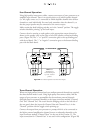
Note: Both switches
should be in “Bridged”
position – this is Two-
channel operation mode.
A jumper is used to
connect both pairs of
negative (“-”) terminals.
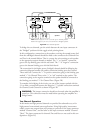
Note: Switch between
Ch. 1 & Ch. 2 should
be in “Normal” position .
Switch between Ch. 3
& Ch. 4 is in “Bridged”
position – this is Three-
channel mode. A jumper
is used to connect the
Ch. 3 & Ch. 4 speaker
negative (“-”) terminals.
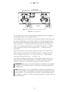
Note: Both switches
should be in the “Normal”
position – this is Four-
channel operation.
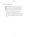
Figure 2 System Connections
Citation 7.0 Controller
Citation 5.1
Amplifier
Citation 5.1
Amplifier
Citation 5.1
Amplifier
Subwoofer
Speakers
Front Channel
Speakers
Citation
Dual Drive
™
Dipoles