


8 FRONT PANEL CONTROLS
0
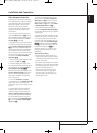
Main Power Switch: Press this button to
apply power to the AVR. When the switch is
pressed in, the unit is placed in a Standby
mode, as indicated by the orange LED
2
.This
button MUST be pressed in to operate the unit.
To turn the unit off completely and prevent the
use of the remote control, this switch should be
pressed until it pops out from the front panel
so that the word “OFF” may be read at the top
of the switch.
NOTE: This switch is normally left in the “ON”
position.
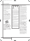
1
System Power Control: When the Main
Power Switch
0
is “ON,” press this button to
turn on the AVR; press it again to turn the unit
off (to Standby). Note that the Power
Indicator
2
will turn blue when the unit is on.
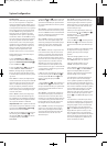
2
Power Indicator: This LED will be
illuminated in orange when the unit is in the
Standby mode to signal that the unit is ready to
be turned on.When the unit is in operation, the
indicator will turn blue.
3
Headphone Jack:This jack may be used to
listen to the AVR’s output through a pair of
headphones. Be certain that the headphones
have a standard 6.3 mm stereo phone plug.
Note that the speakers will automatically be
turned off when the headphones are connected.
4
Digital Optical 3 Input: Connect the
optical digital audio output of an audio or video
product to this jack.When the Input is not in use,
be certain to keep the plastic cap installed to
avoid dust contamination that might degrade
future performance.
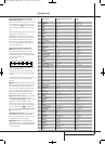
5
Speaker/Channel Input Indicators:
These indicators are multipurpose, indicating
either the speaker type selected for each channel
or the incoming data-signal configuration.The
left, center, right, right surround and left
surround speaker indicators are composed of
three boxes, while the subwoofer is a single box.
The center box lights when a “Small” speaker is
selected, and the two outer boxes light when
“Large” speakers are selected. When none of
the boxes are lit for the center, surround or
subwoofer channels, no speaker has been
selected for that position. (See page 16 for more
information on configuring speakers.) The letters
inside each of the center boxes display active
input channels. For standard analog inputs, only
the L and R will light, indicating a stereo input.
When a digital source is playing, the indicators
will light to display the channels begin received
at the digital input.When the letters flash, the
digital input has been interrupted. (See page 15
for more information on the Channel Indicators).
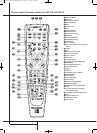
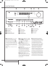
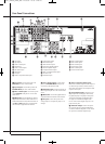
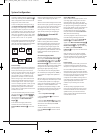
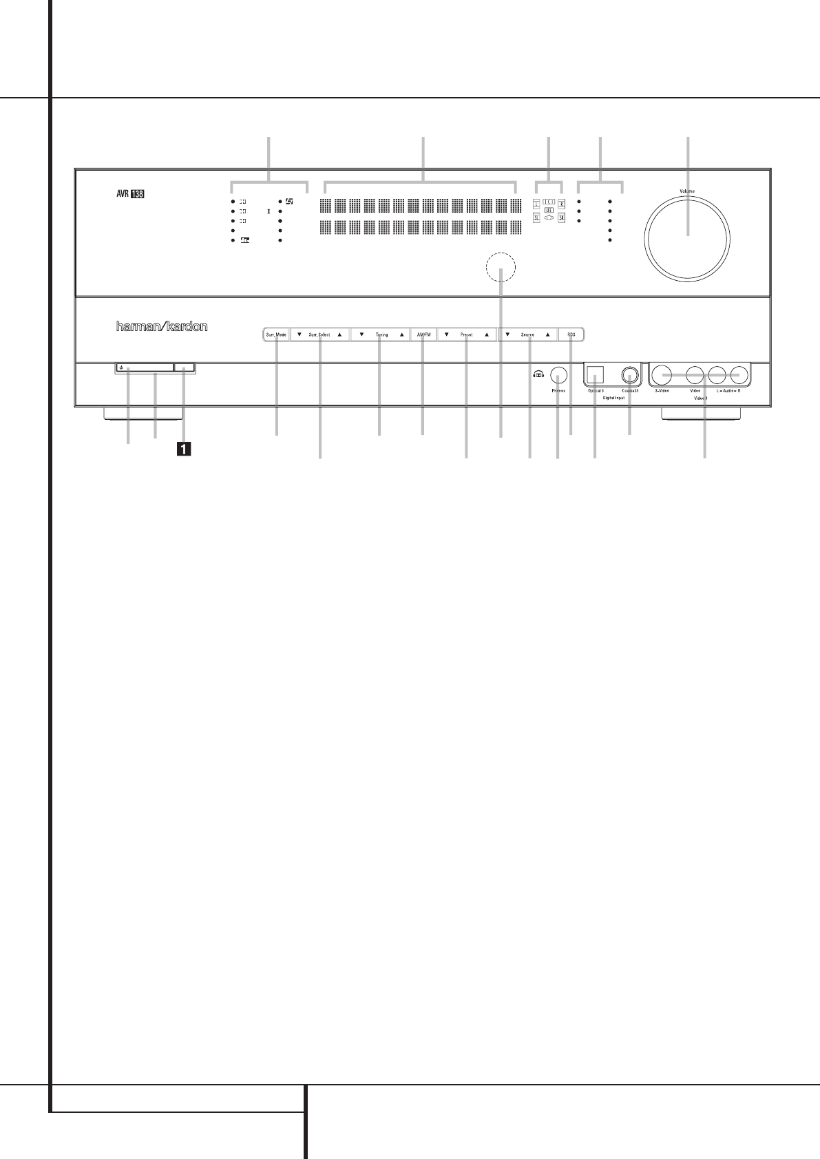
Front Panel Controls
0
1
2
3
4
5
6
7
8
9
A
B
C
D
E
F
G
H
I
J
Main Power Switch
System Power Control
Power Indicator
Headphone Jack
Digital Optical 3 Input
Speaker/Channel Input Indicator
Surround Mode Group Selector
Tuning
Tuner Band Selector
Preset Stations Selector
Input Source Selector
RDS Select Button
Surround Mode Selector
Surround Mode Indicators
Remote Sensor Window
Main Information Display
Digital Coax 3 Input
Video 3 input jacks
Volume Control
Input Indicators
1
67
G
9
D
F
I
J
1
6
C
7
8
B
H
2
4
A
5
E
3
DIGITAL LOGIC 7
VID 1 DVD
CD
FMAM
TAPE
VID 2
VID 3
PRO LOGIC
3 STEREO DSP
5 CH. STEREO
SURR. OFF
6 CH
38277_AVR138_DVD28_ENG 23/07/08 18:36 Side 8