


amplifier. For a temporary adjustment when a signal generator and voltmeter are not available, use an FM tuner and tune
it to an unused station as your signal source, and connect the output to the amplifier as described above. Connect the
amplifier output to a small full range speaker. Turn the amplifier level controls full down and turn the amplifier on. Turn
up the level control until you hear a signal through the speaker. Alternate adjusting R8 and the input control until you have
the level control full. There should be a very low output from the amplifier if any is detected at all.
MODULE REPLACEMENT
WARNING: Only a competent technician should attempt the following procedure.
The amplifier modules have been designed to eliminate the need for a special work place if a field exchange becomes
necessary. All wire connections are made by quick connect terminals. The following tools are needed:
Allen wrench, long reach 9/64
Allen wrench, long reach 7/64
Phillips screwdriver #1 tip
Thin nose pliers
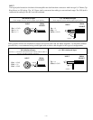
Remove the Phillips head screws located on the rear panel, which secure the input jacks. Remove the two 9/64 Allen
screws located between the heatsink fins along the top edge on each side, which fasten the cover. Three more screws hold
the heatsink to the chassis; remove these screws and the level control knob. Unplug the gray cable which connects the
mono input signal to Channel 2. Tilt the rear of the heatsink up and disengage the assembly from the chassis. Pull the
heatsink away from the chassis to extend the wires. Disconnect the output wires from the binding posts and the power
wires from the module. Remove the module from the heatsink.
Install the new module on the heatsink. If it is Channel 1, set the Ground and Mono switches to the left (looking from the
rear of the module) and reattach the gray mono cable. To reduce the chance of assembly errors in high stress situations,
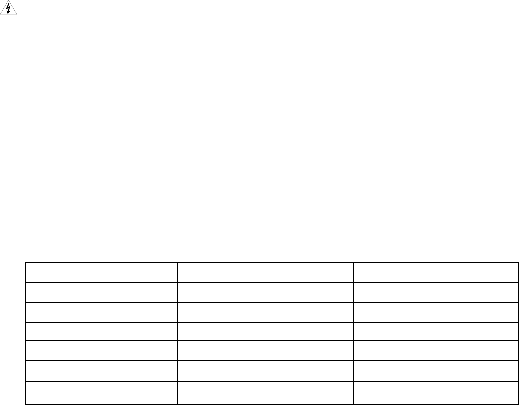
the main AC terminals are sized to accommodate only the correct wires. Reconnect the wires to the terminals as follows:
Wire Color Function Terminal/Size
Red Output Red Binding Post, 1/4"
Black Output Ground Black Binding Post, 1/4"
Orange (two) High Voltage AC AC1, AC2, 1/4"
White/Orange High Voltage Center Tap CT1, 1/4"
Blue (two) Low Voltage AC AC3, AC4, 1/8"
White/Blue Low Voltage Center Tap CT2, 1/8"
– 16 –