


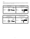
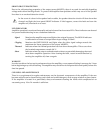
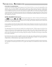
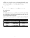

Output Short Protection
The Short detector monitors the Drive Signal and Output Signal levels and shuts down that channel when a shorted
output condition is detected. Recovering from the Short protection requires turning the amplifier off to reset. The
comparator U4B monitors the Drive Signal and goes low when the drive level is sufficient to clip the output stage. This
drive signal clip status is connected to the input of U4A on pin 7, the Output Signal is connected to the input of U4A
on pin 6. The output of U4A goes low when pin 7 is low and pin 6 is near zero. This condition, indicating high drive
voltage and low output voltage, occurs only when the output is shorted. If the output of U4A is low for the time sufficient
for C26 to charge, then U4C latches low activating the protection switch Q1 and lighting the indicator CR1. The output
of U4C is held low by CR14 and will reset only after the power is turned off.
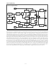
Shut Down
Switch
Q5, Q4
Comparator
U4A
Short
Indicator
CR1
Comparator
U3B
Output
Signal
Drive
Signal
Short Latch
U4C, CR14
Clip Detector
U3A
Clip Detector
U4A
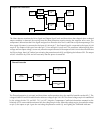
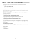
Thermal Protection
Temp
TS1, R25
Comparator
U5B
Soft Start Switch
Q1
THERMAL Indicator
CR2
The Thermal protection is activated, and shuts down audio operation when the amplifier heatsink reaches 90° C. The
voltage divider R22 and R23 establishes the reference voltage on pin 5 of U5B. The control voltage on pin 4 is established
by the voltage divider TS1 and R25. TS1 is a NTC (Negative Temperature Coefficient) thermistor mounted on the
heatsink. As TS1 warms and the resistance falls, the voltage on pin 4 rises. When the voltage on pin 4 exceeds the voltage
on pin 5, the output on pin 2 goes low activating the protection switch Q1 and lighting the THERMAL indicator.
– 14 –