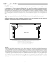
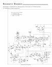
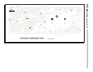
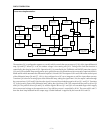
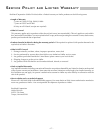
CLIP Indicator
CR3
LED Driver
U5C
Clipping
Detector
U5A
Drive
Signal
Clipping Indicator
The CLIP indicator is driven by the buffer U5C which is controlled by the comparator U5A. The voltage divider R56 and
R57 establishes the reference voltage for the Clipping detector at pin 7 of U5A. The reference voltage scales the output
of U5A to indicate when the Drive Signal at pin 6 demands in excess of the available voltage or current of the output
stage. The output of U5A is stretched by R55 and C30 to prevent the CLIP indicator CR3 from flickering. Hysteresis is
applied to the LED driver U5C by R53 to stabilize the output during input transitions.
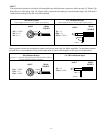
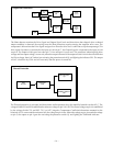
Signal Present Indicator
The SIGNAL indicator is controlled by the comparator U5D and the transistor Q8. The amplifier output is connected
to the input pin 9. The voltage divider R58 and R59 scales the output voltage to change the comparator output state at
an equivalent input voltage of 30mV, with the level controls set for full gain. The output at pin 14 controls the transistor
Q8 to shunt across and turn off the LED CR4.
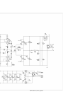
CALIBRATION
WARNING: Only a competent technician should attempt the following procedure.
Bias:
The bias control establishes the quiescent Class AB output current of the amplifier. The bias should not need
readjustment from the factory setting; however, if the amplifier is repaired and output devices have been changed, or
if the two channels of the amplifier do not run at the same temperature, calibrating the bias is necessary. Disconnect
the power to the amplifier before removing the cover. To adjust the bias, disconnect the input and speakers and remove
the jumper JW7. Connect an amp meter across the exposed pins. Adjust R136 to get a current reading of 100 mA for
the P1500, 200 mA for the P3000.
WARNING: Only a competent technician should attempt the following procedure.
Common Mode Rejection:
The input common mode null is adjusted by the trim pot R8. The CMRR should be greater than 75dB below rated output.
If the CMRR requires adjustment, feed the amplifier input with a common mode signal and adjust R8. Disconnect the
power to the amplifier before removing the cover. Use a sinewave generator set to 1 volt output at 1kHz. Connect the
generator signal output to the tip and ring of a 1/4" plug and ground to the sleeve. Plug this into the amplifier input.
Connect an AC voltmeter to the amplifier output binding posts. Adjust R8 to give the lowest voltage output from the
SIGNAL
Indicator
CR4
LED Driver
Q8
Signal
Detector
U5D
Amplifier
Output
– 15 –