


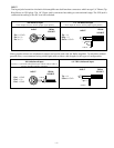
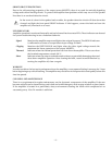
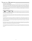
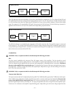
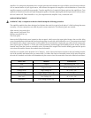

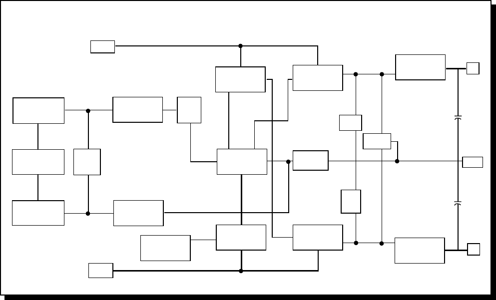
The transistor Q1 is configured to operate as a switch which controls the current source, Q103, of the input differential
amp, Q6 and Q7. When Q1 is off, the emitter voltage is low turning off Q103. Timing of the Soft Start function is
controlled by the charging time of C29. Operation of Q1 is controlled by the THERMAL and SHORT protection circuits.
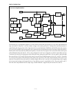
U1A and U1B are buffer amps configured as unity gain followers which feed the resistive network comprised of R24A,
R24B and R6 which attenuates the differential input at U2A and U2B. The output of U2A and U2B is taken to the inputs
of the differential amp Q6 and Q7, U2A is also configured as a DC servo integrator to null the input offset currents.
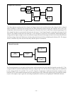
Transistor Q6 is the non-inverting input of the differential amp, taking the signal from U2A, the output is taken through
the current mirror, Q105 and Q104 where the signal is inverted, then feeds the negative driver Q11 and Q12. Transistor
Q7 is the inverting input of the differential amp, taking the signal from U2B. This output feeds the positive driver Q9
and Q10. The positive drivers Q9 and Q10, and the negative drivers Q11 and Q12 are cascoded stages which supply
drive current and voltage to the output devices. Class AB bias current is controlled by R136. The network R1 and C1
form the short loop feedback for the output stage. Global feedback is supplied by the network R10 and C8.
+18V
Positive Input
Buffer
U1A
Balanced Signal
Negative Input
Buffer
U1B
Level
Adjust
R24 A, B
Positive Buffer, DC
Offset Integrator
U2A, R11, C21,
C22
Negative Buffer
U2B
CMRR
Adjust
R8
Differential Amp
Q6, Q7
Current Mirror
Q104, Q105
Positive Driver
Cascode
Q9, Q10
+ –
Feedback
Network
Drive
Signal
Local
Feedback
Bias
Adjust
R136
Positive Output
Q4, Q115
B+
Output
B–
Negative Output
Q5, Q116
Negative Driver
Cascode
Q11, Q12
Current Source
Q103
Protection Switch,
Soft Start Delay
Q1, C29
–18V
CIRCUIT OPERATION
trans•
nova
Implementation:
– 13 –