I NTRODUCTION
– 1 –
The Hafler P1500 and P3000 are two channel professional power amplifiers. Passive cooling with large heatsinks
is used for low mechanical noise. Our patented trans•nova circuit topology and MOSFET output stage ensures
trouble free, long term operation and is backed by our five year warranty.
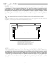
This manual contains information on using the P1500 and P3000 amplifiers. It is organized into three main
sections. “Installation” covers the location and connection of the amplifier in the system. Like many precision
components careful attention to the initial setup can yield dividends in higher performance and trouble-free use.
“Operation” covers the controls and features of the amplifiers and how to use them to get the best effect. The
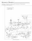
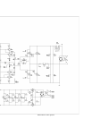
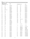
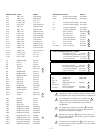
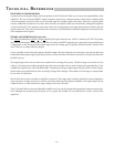
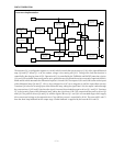
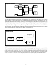
“Technical Reference” section contains field service information. In addition to the schematic and parts list there
are block diagrams and an explanation of circuit operation useful for technicians. We strongly urge reading over
the Installation and Operation portions of this manual before putting the amplifier into service.
The circuitry used in the P1500 and P3000 is the latest refinement of our trans•nova (
TRANSconductance NOdal
Voltage Amplifier, US Patent 4,467,288) circuit. It has been proven to offer sound quality to satisfy the most
analytic audiophile or the most demanding professional. The natural sound and realistic reproduction have made
trans•nova amplifiers preferred in many critical installations. Since our pioneering use of MOSFETs in the DH-
200 amplifier, they have proven extremely fault tolerant even in abusive situations. This sturdiness enables the
amplifier to drive reactive speaker loads without the performance and sound penalties imposed by elaborate
protection schemes.
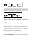
Specialized circuits prevent damage to the amplifiers and speakers without affecting the audio signal. A soft start
circuit prevents sending potentially destructive turn-on and turn-off transients to the speakers. A thermal sensing
network monitors the heatsink temperature and shuts down the amplifier to protect from excessive operating
heat. The need for internal fuses has been eliminated; a sensing circuit monitors the output and shuts down
operation when it detects a short in the output load.
Each channel of these amplifiers is built as a self-contained module which only requires mounting the heatsink
and connection to the chassis-mounted transformer and binding posts to be fully functional. The circuit board
contains all the operational components. This modular arrangement simplifies construction and improves service
accessibility. The circuit board assembly makes extensive use of surface mount components in the low power
portion of the audio circuitry. Automated equipment is used to place and solder the components which yields
greater uniformity and reliability.
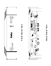
The front panel has controls for input level adjustment and the power switch. In addition, LED indicators give
a visual representation of the operating status of each channel. The THERMAL and SHORT indicators light to show
when these protection circuits have been activated. The CLIP indicator helps prevent damaging the speakers by
showing when the amplifier is overdriven. The SIGNAL indicator lights to show the presence of an audio signal.