


HEADPHONE
AMPLIFIER
AM/FM TUNER
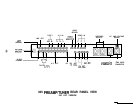
The Headphone Amplifier utilizes a separate special purpose operational amplifier to drive the high
current demands of headphone operation. This provides the extra power necessary for driving difficult
headphone loads, and leaves the main signal path uncompromised for signals to power amplifiers.
The Headphone jack is equipped with a sensing switch that automatically turns off the Line Output when
headphones are plugged in.
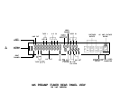
Antenna signal input to the FM Tuner section is via either balanced 300 ohm thumb-screws, or via an
unbalanced 75 ohm F-Type connector. Antenna signal input to the AM Tuner section is via unbalanced
thumb-screws.
The FM front end features dual-gate FET’s for exceptional rejection of spurious noises and the reduction
of IM distortion in the presence of high level signals. Tuning is accomplished via a voltage controlled
varactor diode, driven by a digitally synthesized Phase Lock Loop system. Twin ceramic filters in the IF
stage have flat group delay characteristics, improving selectivity, phase linearity, and lowering distortion.
The audio output features multi-stage multiplex filters for removing the 19 kHz pilot tone.
ADDITIONAL INFORMATION
GENERAL
TROUBLE-
SHOOTING
HINTS
GROUND LOOPS
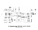
Operation of the 945 Preamp/Tuner is straightforward, and few operational problems, should be
encountered after a thorough reading and understanding of the owner’s manual. The Functional Block
Diagram provides an excellent “picture” of the signal flow, and should be referred to along with the
descriptive text.
If all controls are in the intended position and the Ready light is green, check all system power
connections, interconnecting and speaker cables, and fuses. The 945 does contain one internal power
fuse, but this fuse should not generally blow unless a malfunction has occurred. This fuse should be
replaced only by aqualified technician, and only with the exact type and rating of fuse originally supplied.
If this fuse is replaced and blows again within a short time, disconnect all power immediately and return
for service.
If all controls, fuses, cables, etc. seem to be functioning properly, a process of one-at-a-time component
substitution should be employed until the defective unit is identified. If only one channel is not functioning
properly, a one-at-a-time reversal of interconnect and speaker cables from left to right should reveal the
malfunctioning component.
Ground loops are characterized by a low level hum or buzz in the system. Loops are caused by a voltage
potential difference between two points in a ground circuit, and aggravated when multiple paths for a
given circuit exist. Noise-free audio performance is dependent upon all grounds being at the same
potential, with a single path for each ground connection. Ground loops can exist in two forms: 1) loops
created in audio interconnects, and 2) loops created between earth grounded chassis.
Mounting components to a rack with metallic rails may introduce ground loops between associated
equipment, because the rails can introduce a second ground path. The extent of this problem will depend
on the grounding arrangements of associated equipment. Ground loops can occur in non-rackmounted
equipment, though it is less common.
If ground loops occur, and any other component in the system has a three wire grounded power cord,
the first step should be to use a ground adaptor (with the ground tab or wire of the adaptor notconnected)
on the power cord plug of the preamplifier. DO NOT cut off the grounding pin on the plug! It may be
necessary to use additional adaptors on other grounded components if more than two components are
earth grounded. (In other words, only one earth ground per system should exist.) Another potential
source of multiple earth grounds is from coaxial antenna or cable service feeds for FM or video sources,
which usually are (and should be) earth grounded. The ground adaptor(s) should cure this grounding
problem as well.
-17-