


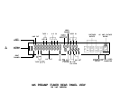

ANTENNA
CONNECTIONS
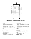
INITIAL POWER-
UP/MUTING
SYSTEM
AUDIO LINE LEVEL
INPUTS
AUDIO LINE
LEVEL OUTPUTS
VIDEO
SWITCHING
A simple
"T"
shaped dipole ribbon antenna has been provided for FM reception. Connect its leads to the
rear panel terminals marked “FM 300 OHM”. For best results, the “arms” of this antenna should be fully
extended, and mounted flat against a wall or equipment cabinet.
A “loop” type antenna has been provided for AM reception. It is to be connected to the rear panel
terminals marked “AM ANT” and “GND”. This antenna is attached at one end by a snap-in hinge. As this
antenna is directional, it will usually be beneficial to allow the antenna to swing away from the body of
the tuner, orienting it for best reception. The antenna may be completely detached for maximum freedom
of placement, by carefully prying it loose from the plastic hinge.
The antennas supplied will yield satisfactory reception in most situations. For further information
regarding these antennas, as well as alternate antenna types, consult the section “Additional Information”.
As soon as the 945
Preamp/Tuner
is plugged into AC power, the Power Switch will glow amber,
indicating a low power stand-by mode. When the unit is turned ON via the front panel Power Switch or
Remote Control, the Power Switch light will turn green, and the Volume Control Indicator will begin to
flash green. Once the muting delay period has passed and the power supply has stabilized, the light
will turn steady green (unless MUTE was selected when the unit was previously turned off). The
Preamp/
Tuner is now ready to enjoy.
The muting will reactivate immediately (and the Power Switch turn amber) upon loss of AC line voltage,
operating the Power Switch, or if line voltage falls below a level which precludes proper operation of the
Preamp/Tuner’s circuitry.
All selected operating modes that were set when the unit was turned off will resume when the power is
turned on again. It will not, however, “remember” some of the set operating modes if AC power is lost
entirely. Tuner Presets and selected inputs will be retained in memory for a few days.
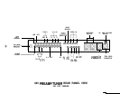
PREAMPLIFIER SECTION
The audio input jacks labelled CD, AN1 , A/V2, and AN3 are identical line level inputs. These inputs,
along with the internal AM/FM Tuner, are selected via the front panel Input Selector buttons or via the
Remote Control. The selected function will be indicated by a green light on the corresponding button.
LINE OUT: This output feeds the selected input signal to the power amplifier.
A/V OUT: This output feeds any selected audio input signal (except A/V3) to a video recorder. This
may be done to allow an audio recording along with a video signal, or for an audio-only recording.
A/V3 is blocked from this output to avoid possible feedback conditions. A/V3 is for playback (viewing)
purposes only, or is recommended to be used as the recording (destination) unit when dubbing from one
video device to another.
The video input jacks labelled Video
1,
Video 2, and Video 3 are selected simultaneously with the
corresponding audio AN inputs. When A/V1 or A/V2 is selected, the video signal is fed to both the Video
Record and Video Monitor Outputs through separate buffer amplifiers. In most cases, the Video Monitor
i
Output will be connected to the video input of a television receiver/monitor, and the Video Record Output
1
will be connected to the video input of a video recorder for dubbing purposes.
When A/V3 is selected, the video signal is fed to the Video Monitor Output, but the Video Record output
is de-activated to prevent possible feedback conditions. AN3 is for playback (viewing) purposes only,
or is recommended to be used as the recording (destination) unit when dubbing from one video device
to another.
-12-